Pilz PSS SB M12 TERMINATOR User Manual
Pss sb sub-d-fo1
PSS SB SUB-D-FO1
Order Number: 311 053
1. Product Description:
The SafetyBUS p FO transceiver converts electrical signals of a SafetyBUS p interface into optical signals. The data
transmission is bi-directional, data-transparent, and in half-duplex mode. SafetyBUS p systems with transmission
rates up to 500 kBit/s are supported.
The SafetyBUS p FO transceiver can be used for SafetyBUS p devices that provide the supply voltage for the FO
transceiver at the plug connector.
The SafetyBUS p FO transceiver is used with a 50/125µ or 62.5/125µ graded index glass fibre at a wavelength of
850 nm and ST connectors. The optical interface is not necessarily compatible to other FO systems, so the FO
transceivers always should be used as a pair.
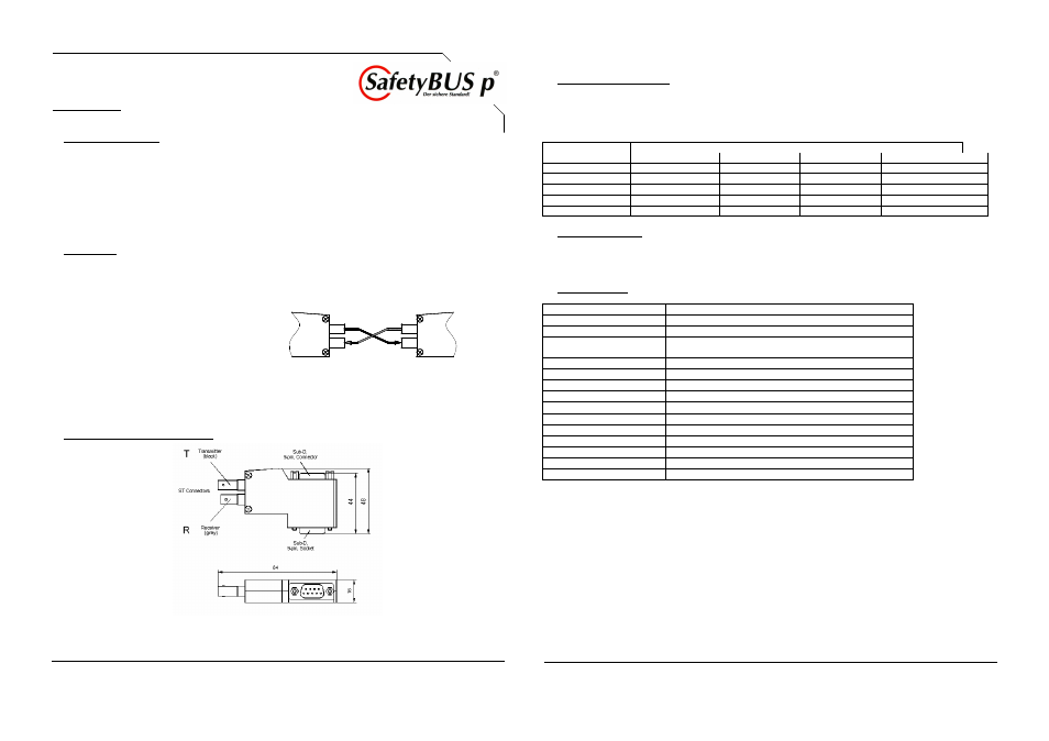
2. Installation:
Connect the SafetyBUS p FO transceiver to the male 9-pin Sub-D connector of the SafetyBUS p interface. Fasten
the fixing screws finger tight. The supply voltage is fed over the SafetyBUS p interface, a maximum of two FO
transceivers can be attached to each SafetyBUS p device. Star shaped structures are not permitted.
Connect the fibre optic cable to the ST connector and secure the connector by a quarter turn of the bayonet lock.
Info! Make sure that both fibres are crossed: The
transmitter (T) is connected to the receiver (R),
and vice versa.
R
T
R
T
CAUTION! Eye Protection: The FO transmitter is a laser with invisible radiation of Class 1M.
Class 1M lasers are only dangerous to human skin and eyes when the radiation is focused by optical instruments.
According to the regulations for the prevention of accidents UVV VBG 93, lasers of Class 1M may be used without
restrictions if looking directly into the laser beam is not intended.
3. Building Up and Measurements:
2011-01 · Technical details are subject to change without notice
4. Length of the Main Line:
The maximum length of the main line (that means the distance between the bus subscribers) is reduced by FO lines.
Each pair of FO transceivers reduces the maximum length of the main line by 35 m.
The following table shows the permitted length of the main lines as a function of the number of FO lines and the
transmission rate.
Transmission Rate
Maximum Length of the Main Line in m
in kBit/s
no FO Line
1 FO Line
2 FO Lines
n FO Lines
500
95
60
25
-
250
250
215
180
250 – (n x 35)
125
500
465
430
500 – (n x 35)
50
1450
1415
1380
1450 – (n x 35)
20
3500
3465
3430
3500 – (n x 35)
5. Connection Cable:
It is not recommend to connect an electrical cable in addition to one or two FO transceivers, as perfect operation is
not guaranteed in special applications. If the application requires an electrical cable to be connected, the cable must
be terminated at both ends by the characteristic impedance.
6. Technical Data:
Wavelength
850 nm
Fibre
50/125µ GI or 62,5/125µ GI
Optical Connector
ST (B-FOC)
Maximum Transmission
4000 m (50/125µ)
Distance
3400 m (62,5/125µ)
Transfer Rate
10 kBit/s – 500 kBit/s
Operating Voltage
5 V DC (±5%), over Sub-D Connector
Current Consumption
70 mA max.
Pin Assignment
2 CAN-L, 7 CAN-H, 5 Shield, 3 OV/CAN-Gnd, 8 Vcc
PullUp, PullDown
390
Ω
each
Terminating Resistor
no
Dimensions
84 x 48 x 16 mm
Operating Temperature
0 to +65 °C
Storage Temperature
-25 to +85 °C
Humidity
10 - 90 % (no condensing)
EMC
CE conform, in accordance with EMC guideline 89/336/EEC
2011-01 · Technical details are subject to change without notice