AXING SPU-21-02 User Manual
AXING Routers
DE
EN
Stand 2010-01-22 - Konstruktions- und Typenänderung vorbehalten - keine Haftung für Druckfehler
State of the art
- Reserving change in design and type - We cannot be held liable for printing errors
2010-01-22
Lesen und aufbewahren
Read and keep
BETRIEBSANLEITUNG
DiSEqC-Umschalter
2 in 1 • 4 in 1 • 5 in 2 • 2× 4 in 1
OPERATION INSTRUCTIONS
DiSEqC-switches
2 in 1 • 4 in 1 • 5 in 2 • 2× 4 in 1
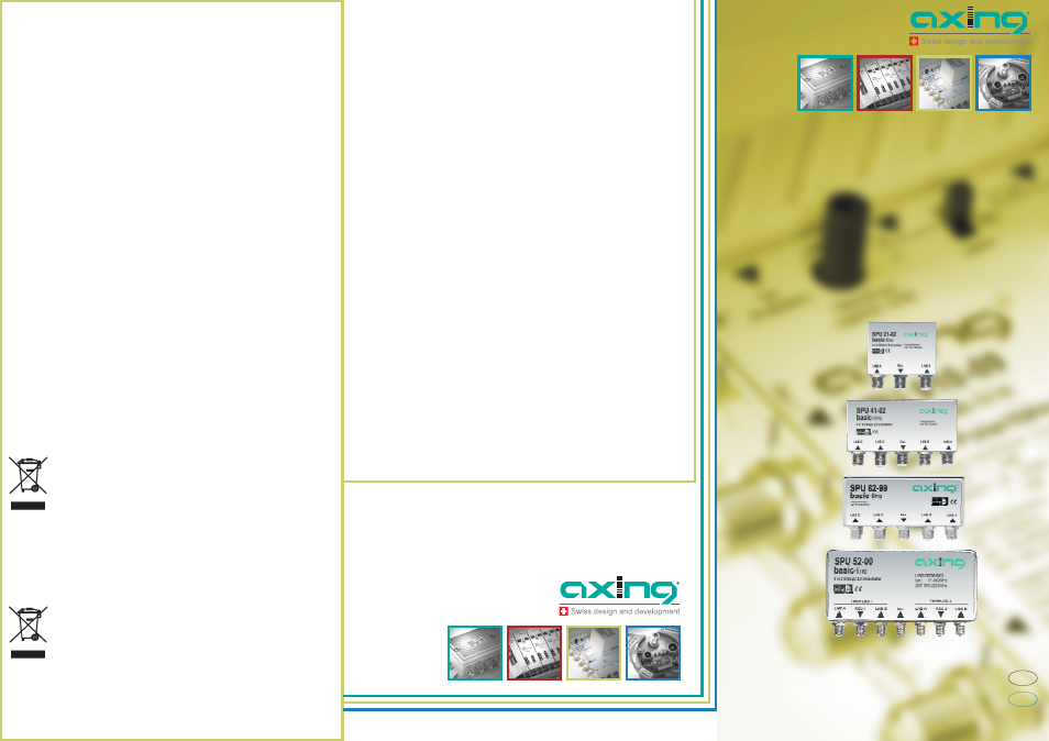
SPU 21-02
SPU 41-02
SPU 82-00
SPU 52-00
Dieses Symbol weist darauf hin, dass das Produkt gemäß WEEE-Richtlinie
(Richtlinie über Elektro- und Elektronik-Altgeräte) (2002/96/EC) und
nationalen Gesetzen nicht über den Hausmüll entsorgt werden darf.
Dieses Produkt muss bei einer dafür vorgesehenen Sammelstelle
abgegeben werden. Dies kann z. B. durch Rückgabe beim Kauf eines
ähnlichen Produkts oder durch Abgabe bei einer autorisierten Sammelstelle
für die Wiederaufbereitung von Elektro- und Elektronik-Altgeräten
geschehen.
Informationen zu Sammelstellen für Altgeräte erhalten Sie bei Ihrer
Stadtverwaltung, dem öffentlich-rechtlichen Entsorgungsträger, einer
autorisierten Stelle für die Entsorgung von Elektro- und Elektronik-
Altgeräten oder Ihrer Müllabfuhr.
This symbol indicates that this product is not to be disposed of with your
household waste, according to the WEEE Directive (2002/96/EC) and your
national law.
This product should be handed over to a designated collection point, e.g.,
on an authorized one-for-one basis when you buy a new similar product or
to an authorized collection site for recycling waste electrical and electronic
equipment (WEEE).
For more information about where you can drop off your waste equipment
for recycling, please contact your local city office, waste authority, approved
WEEE scheme or your household waste disposal service.
WEEE Nr.
DE14023300
WEEE Nr.
DE14023300
Technische Daten:
Frequenzbereich SAT
950…2200 MHz
Eingänge
SPU 21-02
SPU 41-02
SPU 52-00
SPU 82-00
Frequenzbereich terr.
-
-
47…862 MHz
-
2
4
5
2 ×4
Ausgänge
1
1
2
2
Durchgangsdämpfung
typ. 4 dB
Entkopplung LNB A-B
20 dB
-
30 dB
-
Entkopplung LNB A-B-C-D
-
30 dB
-
30 dB
Schaltkriterien
DiSEqC 2.0
Anschlüsse
F
Maße ca.
120×70×30 120×110×30 150×122×30 120×110×30
³
³
³
³
Technical Data:
Frequency range SAT
950…2200 MHz
Frequency range terr.
-
-
47…862 Mhz
-
Inputs
2
4
5
2 ×4
Outputs
1
1
2
2
Through loss
typ. 4 dB
Isolation LNB A-B
20 dB
-
30 dB
-
IsolationLNB A-B-C-D
-
30 dB
-
30 dB
Switching signals
DiSEqC 2.0
Connectors
F
Dim. appr.
120×70×30 120×110×30 150×122×30 120×110×30
SPU 21-02
SPU 41-02
SPU 52-00
SPU 82-00
³
³
³
³
É
Safety advice:
·
·
·
·
Installation and repairs to the equipment may only be carried out by
technicians observing the current VDE guidelines. No liability will be
assumed in the case of faulty installation and commissioning.
To prevent damage to your equipment and to avoid possible peripheral
damages, the devices foreseen for wall mounting may only be installed on a
flat surface.
Choose the location of installation or mounting such that children may not
play unsupervised near the equipment and its connections. The location of
installation or mounting must allow a safe installation of all cables
connected. The mains cable as well as feeder lines may not be damaged or
clamped by objects of any kind.
If possible - please install the Multiswitch underneath the roof or at any dry
location. If installed open-air,
to use watertight connectors!
make sure
É
Sicherheitshinweise:
·
·
·
·
Die Installation des Geräts und Reparaturen am Gerät sind ausschließlich
vom Fachmann unter Beachtung der geltenden VDE-Richtlinien
durchzuführen. Bei nicht fachgerechter Installation und Inbetriebnahme wird
keine Haftung übernommen.
Um Beschädigungen am Gerät selbst oder an Peripheriegeräten
vorzubeugen, dürfen Geräte, die zur Wandmontage vorgesehen sind nur auf
flachen Oberflächen montiert werden.
Wählen Sie den Montage- bzw. Aufstellort so, dass Kinder nicht
unbeaufsichtigt am Gerät und dessen Anschlüssen spielen können. Der
Montage- bzw. Aufstellort muss eine sichere Verlegung aller
angeschlossenen Kabel ermöglichen. Das Netzkabel sowie Zuführungskabel
dürfen nicht durch irgendwelche Gegenstände beschädigt oder gequetscht
werden.
Montieren Sie nach Möglichkeit den Multischalter unter einem
Dachvorsprung oder an einem trockenen Platz. Bei Montage im Freien
unbedingt auf wasserdichte Verschraubungen der Anschlüsse geachtet
werden!
muss