CIRCUTOR CVM-NET Series User Manual
Cvm-net, Cvm-net power analyzer
CVM-NET
M98229901-03-14A
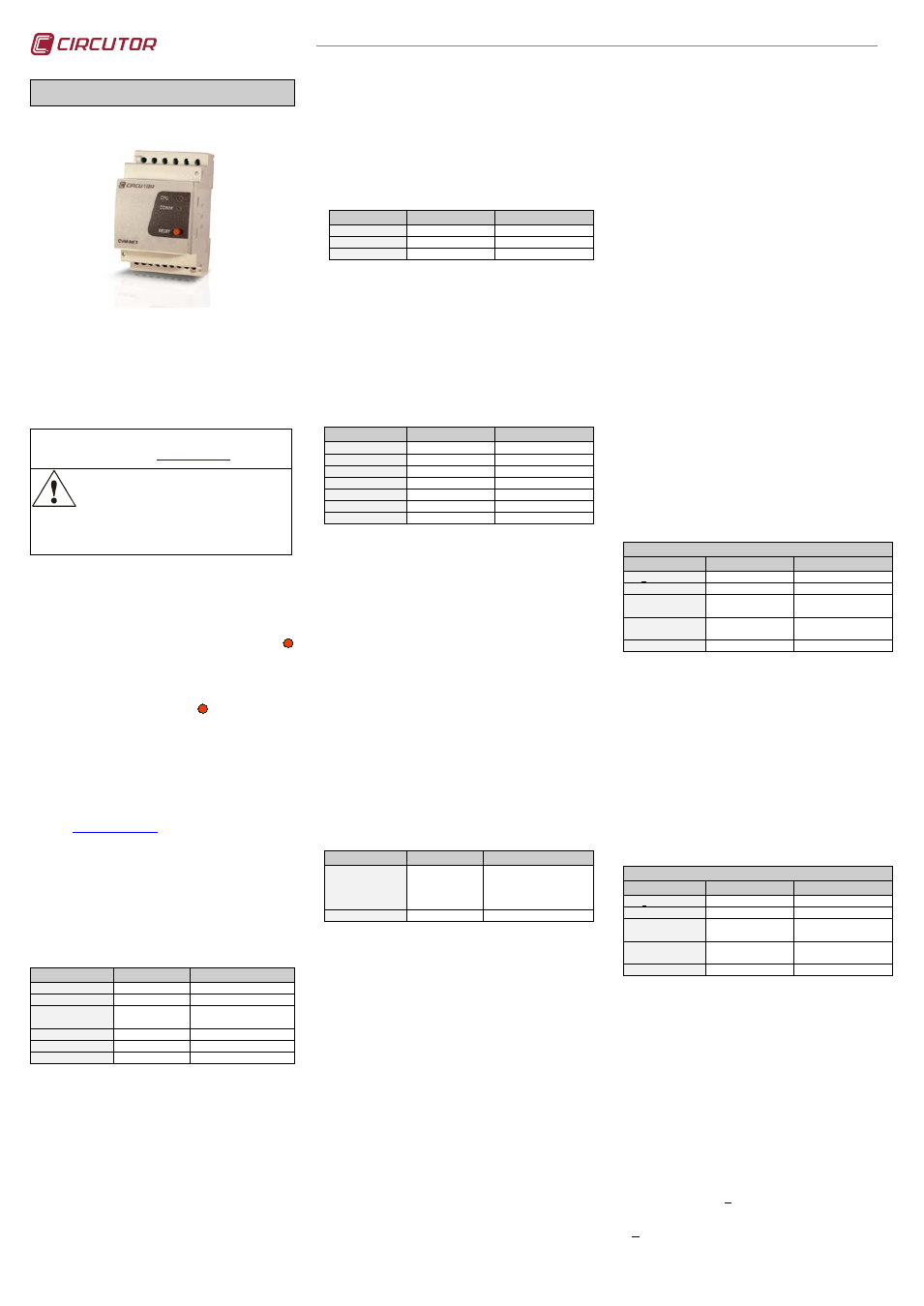
CVM-NET POWER ANALYZER
CVM-NET is an instrument that measures and
calculates the primary electric parameters in three-
phase industrial power grids (balanced or unbalanced).
It is measured in true RMS values, using three AC
voltage inputs, and three AC current inputs (through
current transformers I
n
/ 5 A) .
The measured and calculated parameters are shown in
the table of variables.
You can find this manual in electronic format on the website
o
Before performing any maintenance operations,
connection modifications, repairs, etc., you must
disconnect the unit from the power supply. If you
suspect an operational fault in the unit or in its
protection system, remove the unit from service. The design of
the unit makes it easy to replace in the event of a fault.
1.- KEYPAD
CVM-NET has a single button; it can be used to
functionally reset the unit or to restore default
communication parameters.
To functionally reset the unit, press the button
RESET
for at least one second, and the unit will reset its
system within 5 s.
To restore the default communication parameters
(19200/8N/1 see section 2.1.-), disconnect the auxiliary
power, then press the button
RESET
, and, while holding
the button down, switch the unit back on. After 5 s, the
unit restores its factory settings.
2.- CONFIGURATION
As the unit has no keypad, the configuration settings
must be sent to the device via Modbus/RTU©
commands, or using the CIRCUTOR PowerStudio
Software, which can be downloaded for free from the
website
2.1.- Configuration of configuration settings
Two options are available for this:
2.1.1.- Using the peripheral number
By default, the unit has the following parameters:
3/19200/8/N/1. The following records are available for
changing the peripheral number or speed
of
communications:
Modbus Address
Variable
Valid data window
03E8 Hi
Protocol
0 - Modbus
03E8 Lo
Peripheral number 00 to FF ( 0 to 255 dec)
03E9 Hi
Speed (Baud)
0- 1200, 1- 2400, 2- 4800,
3- 9600, 4- 19200
03E9 Low
Parity
0- No
03EA Hi
Length in bits
1- 8 bits
03EA Low
Stop bits
0- 1 bit
Example of a write command. Changing the peripheral
number. From 03 (3 decimal) to 0F (15 decimal), at 9600 bps.
TX: NP 10 03E8000306 000F 0300 0100 CRC
RX: NP 10 03E80003 CRC
After editing the registers with the new communications
parameters, must be reset the device with the next sentence,
entering in the peripheral number the original slave address (in
this case the number 03).
TX: NP 05 07D01100 CRC
RX: NP 05 07D01100 CRC
2.1.2.- Using the serial number (broadcast)
The serial number of the unit can be found on the side
label of the device (e.g.:3104200679). This number
must be translated into hexadecimal language so that
the sentence can be sent to the unit:
3104200679 (Decimal)
B90657E7 (Hexadecimal)
The parameters to be set using the “broadcast” format
to the 00 peripheral are restricted, as they are only for
configuring the communication settings:
Modbus Address
Variable
Valid data window
0BB8,0BB9
Unit serial number
0 to FFFFFFFF (N)
0BBA Hi
Peripheral number
0 to FF (P)
0BBA Low
Port speed
0- 9600, 1-19200 (V)
Example of a write command. Changing the peripheral number.
From 03 (3 decimal) to 0F (15 decimal), at 9600 bps.
TX: 00 10 0BB8000306 B90657E7 0F 00 CRC
RX: Time Out
2.2.- Transformation ratio settings
The CVM-NET
analyzer
can perform indirect
measurements (using voltage and current transformers).
For this reason, it has an input table for setting the
voltage and current transformation ratios. If the voltage
measurement is performed directly, the ratio is 1/1.
Modbus Address
Variable
Valid data window
044C,044D
Primary voltage
0 to 000186A0 (100.000)
044E
Secondary voltage
0 to 03E7 (999)
044F
Primary current
0 to 2710 (10,000)
0450 Hi
Not used
00
0450 Low
Not used
00
0451 Hi
Harmonic calculation
00 – THD / 01- D
0451 Low
Not used
00
Example of programming voltage ratios; Direct voltage
measurement (230 ph-N), and current transformers with
primary ratio of 400 A.
Primary voltage
1(Dec)
00000001 (Hex)
Secondary voltage
1(Dec)
0001 (Hex)
Primary current
400 (Dec)
0190 (Hex)
Calculating harmonics 00 with regard to the Effective Value
TX: NP 10 044C00060C 000000010001019000000000 CRC
RX: NP 10 044C00060C CRC
Next, reset the unit (see section 2.1.1.-).
2.2.1.- Reading transformation ratios settings
As additional information, the user has a Modbus
command, for reading the transformation ratios setting in
th device:
TX: NP 04 044C0006 CRC
RX: NP 04 0C 00000001 0001 0190 00000000 CRC
2.3.- Maximum demand settings
The power analyzer can calculate the maximum value,
using the sliding window method. This calculation can be
associated to one of the three available variables, as
shown below.
Modbus Address
Variable
Valid data window
04E2
PD calculation
variable
0000 – No Pd
0010 – Active power III
0022 – Apparent power III
0024 – Three-phase current
04E3
Integration time
0 to 003C (0-60 minutes)
Example of maximum demand programming by three-phase
power, with a 15 minute period:
TX: NP 10 04E2000204 0010 000F CRC
RX: NP 10 04E20002 CRC
Next, reset the unit (see section 2.1.1.-).
2.3.1.- Reading maximum demand setting
As additional information, the user has a Modbus
command, for reading the maximum demand setting:
TX: NP 04 04E20002 CRC
RX: NP 04 04 0010 000F CRC
2.4.- Deleting maximum and minimum values
The power analyzer records all the maximum and
minimum values for each parameter measured in the
Modbus/RTU variables table. A command is available
for resetting these records:
TX: NP 05 0836 FF 00 CRC
RX: NP 05 0836 FF 00 CRC
2.5.- Deleting maximum demand
The maximum demand parameter, when calculated
using the sliding window, can be reset, allowing the
calculation to be restarted.
TX: NP 05 0838 FF 00 CRC
RX: NP 05 0838 FF 00 CRC
2.6.- Configuration and use of digital outputs
2.6.1.- Forcing digital outputs
The unit is fitted with two digital outputs, that can be
remotely managed in both their opening and closing
functions.
Forcing Digital Output number 1:
TX: NP 05 0000 XX 00 CRC
RX: NP 05 0000 XX 00 CRC
(Where XX
FF Close / 00 Open)
Forcing Digital Output number 2:
TX: NP 05 0001 XX 00 CRC
RX: NP 05 0001 XX 00 CRC
(Where XX
FF Close / 00 Open)
2.6.2.- Reading the digital output status
The user can request a reading of the digital output
status via Modbus/RTU using the following sentence:
TX: NP 01 0000 0008 CRC
RX: NP 01 01 XX CRC
Where XX
04 Both outputs open
05 Output 1 closed
06 Output 2 closed
07 Both outputs closed
2.6.3.- Digital output settings
Digital outputs, in addition to being remotely managed,
can be used as alarm elements, associated with an
electric variable by a maximum or minimum value, or
fulfil the power pulse function associated with any
power consumption parameter (active or reactive). The
following input table is provided for programming them:
Digital output 1
Modbus Address
Variable
Valid data window
047E, 047F
MAX value or W·h imp Hexadecimal value
0480, 0481
MIN value
Hexadecimal value
0482
Delay
0 to 270F (9,999
Decimal)
0483 Hi
Variable number
00 (See table of
variables)
0483 Low
Not used
00
*When a power variable is selected, the analyzautomatically recognises the
power pulse function and applies the w·h value of the first record.
Example of alarm programming by maximum and minimum
value with voltage VL1. A maximum value of 240 V, a minimum
value of 200 V (the voltage value must be sent multiplied by 10
(as shown in the enclosed variables table), and delay of 10
s are programmed.
Maximum value 2400 (Decimal)
→ 00000960 (Hexadecimal)
Minimum value 2000 (Decimal)
→ 000007D0 (Hexadecimal)
Delay
10 (Decimal)
→ 000A (Hexadecimal)
Var number 01 (Decimal)
→ 01 (Hex)
Not used
00 (Decimal)
→ 00 (Hexadecimal)
TX: NP10047E00060C 00000960 000007D0 000A 0100 CRC
RX: 03 10 047E0006 CRC
Next, reset the unit (see section 2.1.1.-).
Digital output 2
Modbus Address
Variable
Valid data window
04B0, 04B1
MAX value or W·h imp Hexadecimal value
04B2, 04B3
MIN value
Hexadecimal value
04B4
Delay
0 to 270F (9,999
Decimal)
04B5 Hi
Variable number
00 (See table of
variables)
04B5 Low
Not used
00
*When a power variable is selected, the analyzer automatically recognises
the power pulse function and applies the w·h value of the first record.
Example of alarm programming by maximum and minimum
value with voltage VL1. Maximum value: 240 V, minimum value:
200 V (Vx10), and a delay of 10 s.
Maximum value 2400 (Decimal)
→ 00000960 (Hexadecimal)
Minimum value 2000 (Decimal)
→ 000007D0 (Hexadecimal)
Delay
10 (Decimal)
→ 000A (Hexadecimal)
Var number 01 (Decimal)
→ 01 (Hex)
Not used
00 (Decimal)
→ 00 (Hexadecimal)
TX: NP1004B000060C 00000960 000007D0 000A 0100 CRC
RX: 03 10 04B00006 CRC
2.6.4.- Next, reset the unit (see 2.1.1.-).Reading digital
output settings
TX: NP 04 04 047X 0006 CRC
RX: NP 04 0C 00000960 000007D0 000A 01 00 CRC
(X: value of the inicial register for each digital output ).
Document Outline
- 1.- KEYPAD
- 2.- CONFIGURATION
- 3.- TECHNICAL SPECIFICATIONS
- 4.- CONNECTIONS
- 5.- TECHNICAL SERVICE