CIRCUTOR EDS Series User Manual
Eds energy efficiency manager
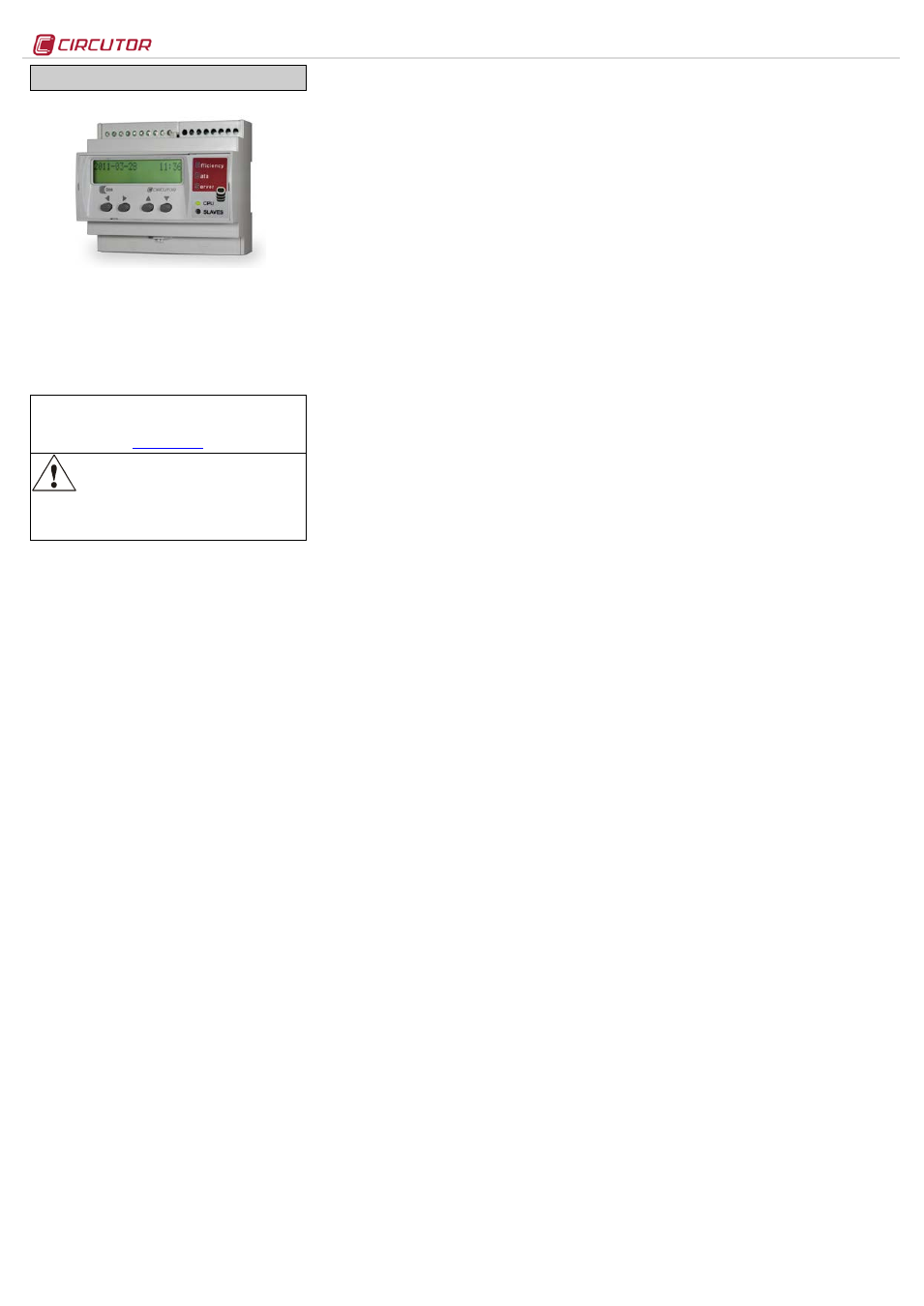
EDS
M98237501-03-13A
EDS ENERGY EFFICIENCY MANAGER
EDS (Efficiency Data Server) is an energy efficiency
manager. The device has an RS-485 communications bus, as
well as 8 digital inputs and 6 digital outputs via relay, which
allow it to communicate with external field devices,
representing and storing the information via its Ethernet
connection and integrated web server. EDS also has a
standard XML server, through which other external
applications can integrate information from the device easily
and intuitively.
This document represents the user and operation manual of the
EDS device. If misplaced, the manual may be downloaded from
CIRCUTOR's web site:
Disconnect the device from the power supply
source before undertaking any form of
maintenance, modification of connections,
repairs, etc. If you suspect any operational
faults in the device or in its protection system, remove the
device from service. The design of the device makes it
easy to replace in the event of a fault.
1.-
Buttons
The front panel of the EDS device has an alphanumeric
LCD
display, along with four function buttons, allowing the user to
navigate through the setup screens of the device.
The buttons have two operating methods:
SHORT KEYSTROKE: when the user presses the function button for
less than two seconds.
LONG KEYSTROKE: when the user presses the function button for
more than two seconds.
The buttons have the following functions:
Scroll left: edit button, scroll the cursor to the left to modify
the numerical or alphanumeric digit.
Scroll RIGHT: edit button, scroll the cursor to the right to modify
the numerical or alphanumeric digit.
Scroll up: the function of this button is to modify the digit
where the edit cursor is located. If there is no cursor on the
screen, move up to the next step of the previous setup option.
Scroll down: the function of this button is to modify the digit
where the edit cursor is located. If there is no cursor on the
screen, move down to the next step of the previous setup
option.
2.-
Setup
The device has two clear setup routes: the first one is related
to the Ethernet integration start-up (IP addressing), and the
second one is related to the setup of the internal application
and possible association with other field devices via the
RS485 bus.
2.1.- Network addressing
EDS is a device with self-detecting Ethernet 10/100BaseTX
connectivity. This means that, in order to integrate the device
into a Local Area Network, it must be provided with a previous
IP addressing configuration.
The user can access the setup parameters via the display and
the function keys on the front panel of the device, or through
the internal setup web site, which is accessible via a
conventional Internet browser.
2.2.- Network parameter setup (Keyboard)
The configuration of the Ethernet network parameters can be
integrally carried out using the function buttons on the front
panel of the device.
To access the setup menu, simultaneously hold down the
keys
Scroll RIGHT, Scroll up and Scroll down for more than two
seconds. The device shows the text
hold on 2 seconds to enter
setup on screen and after 2 seconds the display shows
ENTERING SETUP RELEASE THE KEYS.
2.2.1.- MAC address
After entering the setup menu, the device displays MAC
(Media Access Control) physical address on screen, with a
00:26:45:XX:XX:XX type format. This is an information panel that
the user can use to know the physical address of the device.
To go the next setup screen, press the
Scroll down key.
2.2.2.- DHCP assignment
After entering the setup menu, the device displays
DHCP
(Dynamic Host Configuration Protocol), and shows the by
default
NO option. To modify the option displayed on the
screen, press
Scroll RIGHT until the YES option appears. Do this
twice and the device cyclically displays both options until one
of them is validated.
When the DHCP server is activated via the
YES caption, press
the
Scroll down key to go to the next option.
2.2.2.1.- Client ID -
( DHCP YES )
After activation of the DHCP authentication and the
subsequent validation, the device displays the
Client ID
parameter setup on the screen, which makes reference to the
DHCP name of the device to be logged into the Ethernet
network.
The edit cursor in the first digit is activated via the
Scroll RIGHT
key. This key and the
Scroll up and down buttons can be used
to parameterise an alphanumeric data entry of up to 20 digits.
After the data is entered, press the
Scroll RIGHT key twice until
the edit key disappears, and then validate the data with the
Scroll down key, by going to the next screen.
2.2.2.2.- Assigned values -
( DHCP YES )
After entering the
Client ID name in the device for the first time,
the device displays the parameters assigned by the DHCP
server on the screen. Given that the parameters that are being
edited will not be fixed until the device is configured, it
displays the following fields on the screen, which cannot be
edited (asterisk in upper left hand corner):
-
-
2.2.8.2.- Netmask
-
2.2.8.3.- Gateway
-
2.2.8.4.- Primary DNP
-
2.2.8.5.- Secondary DNS
Given that the DHCP server has not yet been assigned the
Ethernet addressing values (displaying
000.000.000.000), press
the
Scroll down key twice to go the Primary NTP option.
2.2.3.- Primary NTP
The device can be synchronised with a time and date NTP
server (Network Time Protocol) server in the UTC time
system. The device does not display a value by default,
indicating that the synchronisation is completed via DHCP, if
the network server allows this to be done. In this case, it is the
main server.
To configure an NTP server that is different from the DHCP
(
0.0.0.0), press the Scroll RIGHT key, enabling the edit cursor in
the first digit. Set parameters for an alphanumeric data entry
with the
Scroll up and down buttons up to a maximum of 20
digits, indicating an http address or internal or external IP (if
the device has Internet access). After establishing the
parameters, press the
Scroll RIGHT key twice until the edit key
disappears, and then validate the data with the
Scroll down
key, by going to the next screen.
Servers available on the Internet:
-
es.pool.ntp.org
-
pool.ntp.org
2.2.3.1.- Secondary NTP
configuration of the secondary NTP server, carry out the same
procedure as with the Primary NTP.
2.2.4.- Time Zone
To configure the time zone, press the
Scroll RIGHT key to
select the time zone where the EDS device is located.
After selecting the zone, press the
Scroll down key, and go to
the next screen.
2.2.5.- AMB® - Active Mode Bridge
The AMB system reverses the connection process of remote
devices. In this case, it is the equipment that starts the
communication process with the connections server located in
a central computer, by creating a transparent communications
tunnel between the equipment and connection server.
Therefore, the user avoids having to set up and maintain a
fixed IP system or DynDNS in its remote control locations.
2.2.5.1.- Active mode
To configure an access route, press the
Scroll RIGHT key, until
the
YES option appears. When the Active mode is activated via
the
YES caption, press the Scroll down key to go to the next
option.
2.2.5.2.- Act. Mode Host -
( active mode yes )
The “
Act. Mode Host” option determines the IP destination
where the device is actively connected. This is an
alphanumerical field that can be configured with an IP address
or Web routing functions.
2.2.5.3.- Act. Mode Port -
( active mode yes )
The “
Act. Mode port” option is the access port of the central
server, where the AMB connections software has been
installed. This computer must have an access port for
connecting all remote devices, in order to establish a
transparent communications tunnel.
In this case, access to the Internet connection from the central
location will require the use of a connection router, which will
establish a NAT access rule to activate a TCP connection port
in the connection server (connection path).
An access port must be activated in the Internet access
router, which will internally transfer the public communication
frames to the AMB internal connection server and to a port
specified by and known to the user.
The port activated in the communication router must be
configured in the "Port" section.
2.2.5.4.- Act. Mode Identifier -
( active mode yes )
Each element connected to the AMB system must have an
identifier or alias (“
Act. Mode Id.”). This identifier is
alphanumeric and the user must record it in order to enable
the server connection.
An "Identifier" cannot be duplicated within the same
connection server.
2.2.6.- Enable Security
A user and edition password can be activated in the device,
thus avoiding modification of the configuration parameters.
The device displays
NO by default. It should be pointed out that
if the password is activated, it will be present in all the
device's setup and display accesses (keyboard, Web setup
and internal applications).
To modify the option displayed on screen,
Scroll RIGHT until
the option
YES appears. Do this twice and the device cyclically
displays both options until one of them is validated. Establish
the parameters for the alphanumeric data entry with the
Scroll
up and down buttons, up to 20 digits corresponding to the user,
and when the data is validated, repeat the operation with the
password. Validate the data (Scroll right and scroll down).
2.2.7.- Confirm Changes -
( DHCP YES )
The information must be validated to save the setup. The
device displays
yes by default. When the completed
configuration is validated, press the
scroll down key and the
device saves the data and leaves configuration.
If the setup is not saved,
Scroll RIGHT until the no option
appears. Do this twice and the device cyclically displays both
options until one of them is validated with the
scroll down key
2.2.8.- Client ID -
( DHCP NO )*
If the DHCP server is not activated, shown in section 2.2.2.-
DHCP assignment, validate the
NO option using the Scroll
down key and go to the next screen.
2.2.8.1.- IP -
( DHCP no )*
The user configures an IP address for the EDS device using
the configuration option. To do this, press the
Scroll RIGHT key
to activate the edition cursor in the first digit. Press the
Scroll
up and down buttons to establish the parameters of a
000.000.000.000 type numeric data entry. After establishing the
parameters, press the
Scroll RIGHT key twice until the edition
key disappears, and then validate the data with the
Scroll
down key, by going to the next screen.
2.2.8.2.- NetMask -
( DHCP no )*
To configure the (NetMask) setup, press the
Scroll RIGHT key,
activating the edition cursor in the first digit. Press the
Scroll
up and down buttons to establish the parameters of a
000.000.000.000 type numeric data entry. After establishing the
parameters, press the
Scroll RIGHT key twice until the edition
key disappears, and then validate the data with the
Scroll
down key, by going to the next screen.
2.2.8.3.- Gateway -
( DHCP no )*
To configure the Gateway setup, press the
Scroll RIGHT key,
activating the edit cursor in the first digit. Press the
Scroll up
and
down buttons to parameterise a 000.000.000.000 type
numeric data entry. After establishing the parameters, press
the
Scroll RIGHT key twice until the edition key disappears, and
then validate the data with the
Scroll down key, by going to the
next screen.
2.2.8.4.- Primary DNS -
( DHCP no )*
To configure the Primary DNS configuration, press the
Scroll
RIGHT key, activating the edition cursor in the first digit. Press
the
Scroll up and down buttons to establish the parameters of
a
000.000.000.000 type numeric data entry. After establishing
the parameters, press the
Scroll RIGHT key twice until the
edition key disappears, and then validate the data with the
Scroll down key, by going to the next screen.
Document Outline
- 2.1.- Network addressing
- 2.2.- Network parameter setup (Keyboard)
- 2.2.2.1.- Client ID - ( DHCP YES )
- 2.2.2.2.- Assigned values - ( DHCP YES )
- 2.2.3.1.- Secondary NTP
- 2.2.5.1.- Active mode
- 2.2.5.2.- Act. Mode Host - ( active mode yes )
- 2.2.5.3.- Act. Mode Port - ( active mode yes )
- 2.2.5.4.- Act. Mode Identifier - ( active mode yes )
- 2.2.8.1.- IP - ( DHCP no )*
- 2.2.8.2.- NetMask - ( DHCP no )*
- 2.2.8.3.- Gateway - ( DHCP no )*
- 2.2.8.4.- Primary DNS - ( DHCP no )*
- 2.2.8.5.- Secondary DNS - ( DHCP no )*
- 2.2.8.6.- Other setups - ( DHCP no )*
- 2.2.8.7.- Manual Date and Time setup
- 2.2.9.1.- Ping system
- 2.3.- Network parameters setup (Software)
- 3.1.- Web Server
- 3.2.- XML server
- 3.3.- Digital inputs
- 3.4.- Digital outputs
- 3.5.- RS-485 expansion bus
- 3.6.- Additional PS/PSS features
- 4.1.- Type of variables
- 4.2.- EDS variables list
- 4.3.- XML Services
- 4.3.3.1.- Information about one or more variables
- 4.3.3.2.- Information about all the variables
- 4.3.4.1.- Instantaneous value of one or more variables
- 4.3.4.2.- Instantaneous value of all variables
- 4.3.8.1.- Test commands
- 4.3.8.2.- Registration of a listener
- 4.3.8.3.- Deletion or loss of the listeners' list
- 4.3.8.4.- Maintenance of the listeners' list (alive)
- 4.3.8.5.- Reception of events