CIRCUTOR LM50-TCP+ User Manual
Lm50-tcp, Unit centralizator lm50-tcp
LM50-TCP+
M98231601-03-11A.doc1A
UNIT CENTRALIZATOR LM50-TCP+
The LM50-TCP+ is an instrument equipped with 50
voltage-free digital inputs. Through these inputs, using
a master communications software, the user can detect
the logical state of the inputs (open or closed contact),
or otherwise know the number of impulses or
manoeuvres received by an outside impulses emitter
(energy, water, gas meter, etc).
The recorded parameters are shown in the following
variables table (see section 2.3.-).
The purpose of this document is to be a user and operation
manual for LM50-TCP+. It can be downloaded from
CIRCUTOR's website:
www.circutor.es
Before performing any maintenance operations,
connection modifications, repairs, etc., the unit
must be disconnected from the power supply. If
you suspect an operational fault in the unit or in its
protection system, remove the unit from service. The design of
the unit makes it easy to replace in the event of a fault.
1.- DESCRIPTION
The electronic meters have an impulses output that is
proportional to the recorded power. The LM50-TCP+ is
a unit centralizator, equipped with 50 digital inputs
(opto-coupled) for reading the impulses coming from
the meters for electric power, water, gas, etc. The
value of these impulses is associated with 50 memory
records, stored in a non-volatile memory.
Each record has 32 bits (4 bytes), so it can be counted
up to FFFF FFFF hexadecimal, i.e., a total of
4,294,967,295 impulses. When a memory record
reaches this value, the meter is reset back to zero.
The minimum duration of the status change of the
digital input must be of 50 ms. The minimum time
between two successive impulses must also have a
minimum duration of 50 ms. This represents a
maximum sampling frequency of 10 Hz.
2.- COMMUNICATION
For reading or writing the 50 internal records, the
device is equipped with a 10BaseT/100BaseTX self-
detectable Ethernet communication port. The device
has an internal webpage from which the user can
define the network protocol used to communicate with
the management software.
The network protocols that are available and integrated
in the device are: UDP, TCP and Modbus/TCP and to a
completely configurable port (with the exception of
Modbus/TCP that uses port 502 by default).
The device attends to the Modbus/RTU communication
protocol (in TCP and UDP mode) and Modbus/TCP.
In addition to the Ethernet connection, the device is
fitted with an RS485 expansion bus, in order to behave
like an RS485/Ethernet gateway. A maximum of 31
Modbus/RTU slave devices can be connected to this
bus.
2.1.- Ethernet addressing
As the connection from the device to the master
communication system is made using an IP
connection, the addressing parameters must be set.
The setup mode will either by the assignment of a fixed
IP, or by setting a DHCP name.
2.1.1.- Ethernet addressing assignment
For setting up the IP addressing in any of the available
formats, run program IPSetup.exe that is supplied with
the equipment.
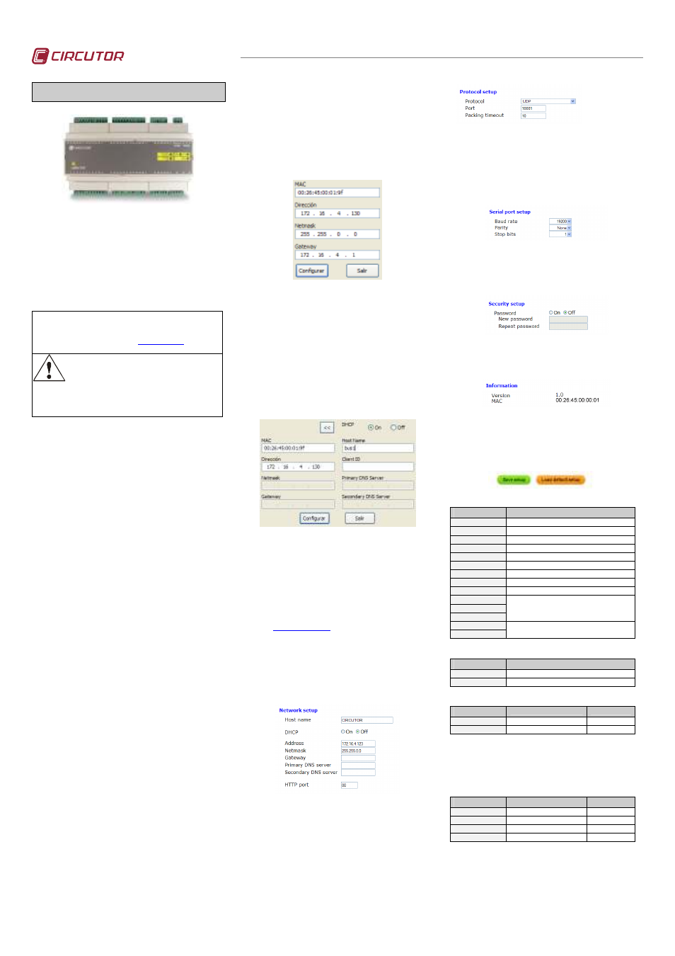
2.1.2.- Fixed IP assignment
To assign the fixed IP address enter the MAC address
shown on the indelible side label attached to the device
with a format of the type 00:26:45:XX:XX:XX. In the
Address
field enter the IP address; do the same with the
(Netmask) and the (Gateway) port if necessary. After
entering the device settings, press “Setup” to send the
configuration to the equipment.
2.1.3.- DHCP IP assignment
To assign the DHCP name, activate this option by
means of the upper right-hand date and select On.
Once the setup fields have been enabled, enter the
MAC
address that can be seen on the indelible side
label attached to the device with a format of the type
00:26:45:XX:XX:XX. In the Address field, enter a
temporary free IP address that is within the working
range of your computer. In Host Name enter the DHCP
name to be assigned to the machine. Optionally, the
user may even set the parameters of the ClientID field.
The device's default VendorID is circutor.
2.2.- Setup webpage
Once connected to the Local Area Network (LAN), and
the IP address or the DHCP name have been set up,
the machine has an internal webpage where all the
parameters relating to the network protocols and
communication speeds of the RS485 bus, can be set
up. To access this internal webpage, it is sufficient to
use a conventional Internet browser and enter the IP
address or the name assigned to the device (for
example
http://172.16.4.130
)
2.2.1.- IP address or DHCP name
By means of the internal webpage, the user can make
any change to the DHCP name or to the IP address
previously assigned to the device, and even change the
http setup access port.
2.2.2.- Network protocol
The equipment can be connected to the master
communications system by means of three types of
network protocol and to a configurable (TCP, UDP or
Modbus/TCP
) port. In the case of the Modbus/TCP
protocol the modification of the port will remain
disabled, staying fixed at 502.
2.2.3.- Setup of the RS485 serial bus
The communications parameters of the RS485
expansion bus are totally configurable for transmission
speed (from 4800 bps to 115.2 kbps), parity (none, odd
or even) and stop bit (1 or 2). Only devices that work
with the Modbus/RTU protocol and a peripheral
number other than 1 can connect to this slave port.
2.2.4.- Setting the setup password
Password can be activated to enable the edition
password. In case to use, the access user is “admin”
and the setup password introduced.
2.2.5.- Device information
The firmware version and the machine address of the
device are shown on the lower part.
2.2.6.- Save changes
Once
any
change
has
been
made
to
the
aforementioned sections, the information must be
saved using the “Save Setup” option. If you wish to
return to the default setup, select “Load default setup”.
2.3.- Modbus memory map
Modbus Address
Variable
0000
Bits 15…0 – Status of inputs 1 to 16 (Binary)
0001
Bits 15…0 – Status of inputs 17 to 32 (Binary)
0002
Bits 15…0 – Status of inputs 33 to 48 (Binary)
0003
Bits 15…0 – Status of inputs 49 to 50 (Binary)
0080
Value of the meter assigned to input 1
0082
Value of the meter assigned to input 2
0084 ... .... 00DE
2 bytes per input value (from 2 to 48)
00E0
Value of the meter assigned to input 49
00E2
Value of the meter assigned to input 50
0578
0579
057A
Shows the version of the equipment. The format
is the following “V1.10” in ASCII values and the
last byte is always 0.
2710
2711
Serial number, always starts with
900 XXX XXX
2.3.1.- Modbus functions
(HEX) function
Description
03 / 04
Reading of input records
10
Writing of several records
2.3.2.- Reading of Modbus records
(HEX) function
Description
Example
AAAA
Reading starting address
0082
BBBB
Number of records
0002
Example of the reading command relating to the value of the
record belonging to digital input 2 (0082Hex).
TX
: 01 04 AAAA BBBB CRC
RX
: 01 04 04 0000 0000 CRC
2.3.3.- Writing of Modbus records
(HEX) function
Description
Example
AAAA
Reading starting address
0082
BBBB
Number of records
0004
CC
Number of bytes sent
08
DDDD DDDD
Value of each record
0000 0064 …
Example of writing command for digital inputs 2 and 3,
recording a value of 100 and 200 in each of them (0000 0064
and 0000 00C8 Hexadecimal)..
TX
:
01
10 AAAA BBBB CC DDDDDDDD DDDDDDDD
CRC
RX
: 01 10 0082 0004 CRC