CIRCUTOR CEP96 Series (Available until stocks) User Manual
Three-phase energy meter cep 96
M98175401-03-13A
THREE-PHASE ENERGY
METER CEP 96
1.- MAIN FEATURES
Electronics-based, Class 1 rated, electrical energy meter, with 4
lines LCD display and also with backlight, for its use in L.V. three-
phase networks, These energy meters are appropriate for any
application that requires the monitoring of partial energy
consumptions.
An additional open collector output can be used as a pulse output.
2.- Installation
This manual contains information and warnings that must
be followed for operating the ENERGY METER safely and
maintaining the instrument in a safe operating condition.
Whether the instrument is not used as manufacturer’s
specifications, the protection of the instrument can be damaged.
Mounting :
Instrument is to be mounted on panel (cut-out 92
+0.8
x 92
+0.8
mm, as
per DIN 43 700). All connections keep inside the cabinet.
Note that with the instrument powered on, the terminals, cover
opening actions or elements removal may allow accessing
dangerous parts. The instrument must not be used until this is
completely installed.
The monitored line should be provided with a circuit breaker or any
equivalent element (fuses) to disconnect the instrument from the
power supply network. This switching device must be placed near
the instrument and will be easily accessible.
The supply and measuring voltage circuits will be both connected
through a wire with a minimum cross-section of 1 m m
2
.
The line of the current transformer secondary will have a minimum
cross-section of 2,5 m m
2
.
CEP-96 has a power supply input which is independent from the
measuring circuit.
Current measurement actions are done through external In / 5 A
current transformers.
3.-
Screen
CEP 96 has two different screens which show the imported and
exported energy. By pressing the
key, you can choose the
imported energy (appears kWh on the fourth line) or the exported
energy (appears -kWh on the fourth line).
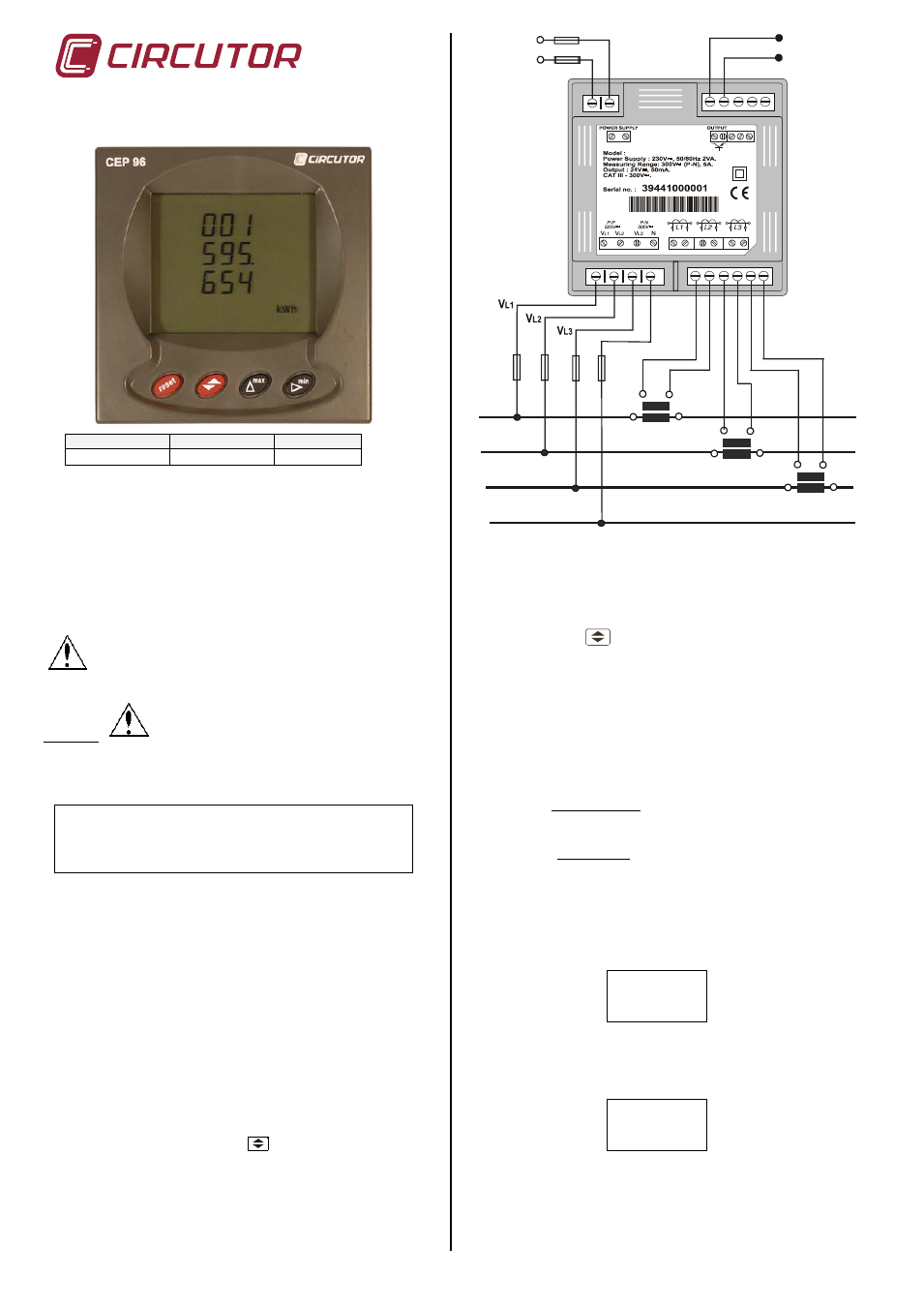
S1
P1
S2
P2
L1
L2
L3
N
S1
P1
S2
P2
S1
P1
S2
P2
N
CEP96
S2 S1 S2 S1 S2 S1
P2 P1 P2 P1 P2 P1
... / 5 A current inputs are isolated.
4.- SETUP
(Simultaneously press the keys MAX and MIN when working in the
main program)
The key
validates the value and passes to the next
menu.
The key MAX permits the user to select among different
options in a menu or to increase a digit when a variable is
being entered.
The key MIN is used to move the cursor along the digits.
NOTE : When you arrive at the last digit, you can move the position
of the decimal point with the "max" key.
When accessing SETUP, the following message in shown in screen
for some seconds:
(1) SETUP UNLOC (SETUP unlocked ) : when the
SETUP is accessed, configuration parameters can be
either visualized and modified.
(2) SETUP LOC (SETUP locked ) : when the SETUP is
accessed, configuration parameters can be visualized but
cannot be modified .
Different options are following shown in a sequential mode:
4.1.- Voltage Transformer Primary
On the screen we read the word "SET VOLT PRI" followed by 6
digits. They allow us setting the primary of the voltage transformer.
SET
VOLT
PRI
027500
From 1 to 100000V
4.2.- Voltage Transformer Secondary
We can now set the value of the secondary of the voltage
transformer. Only three digits are available:
SET
VOLT
SEC
001
From 1 to 999V
If the CEP-96 is directly connected to the mains (without voltage
transformer) the values of primary and secondary must be the same,
for instance 000001/001.
Code
Type
Currents (Ib)
M3 0701
CEP-96 (ITF)
In / 5A
Open collector
Common output
POWER SUPPLY
230V ac