CIRCUTOR MKD Series User Manual
Mkd-itf
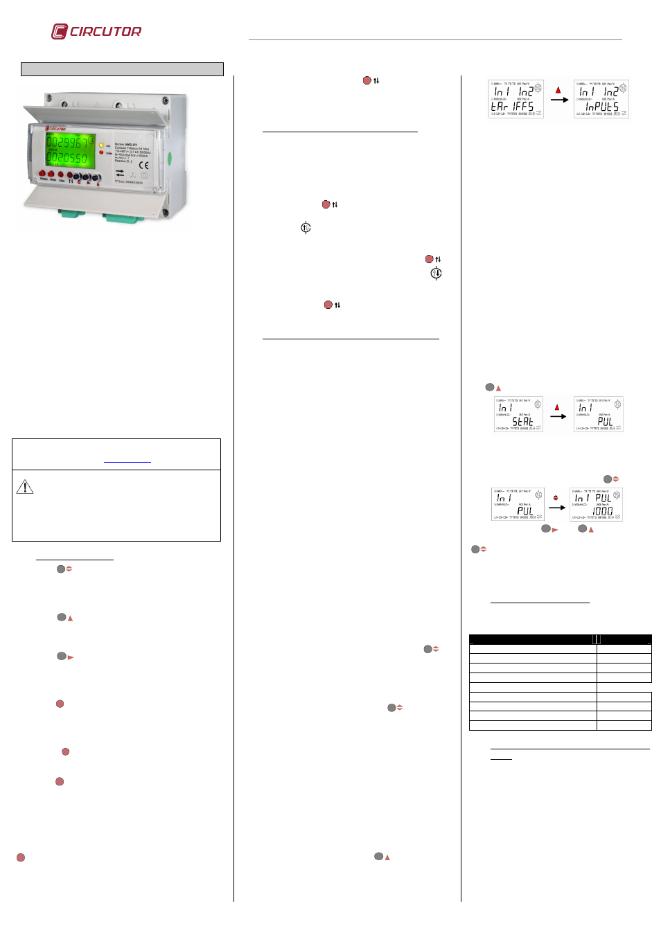
MKD-ITF
M98223701-03-10A
THREE-PHASE METER MKD-ITF
The electronic three-phase energy meter MKD-ITF is
capable of measuring energy in consumption and
generation (four quadrants): active energy (consumed and
generated), inductive reactive energy (consumed and
generated) and capacitive reactive energy (consumed and
generated), in addition to metering partial energies. The
measurement is taken directly in true rms by three current
transformers in L1, L2 and L3 incorporated in the unit. The
power is supplied by the measurement itself between the
phases L1 and L2. The parameters measured and
calculated are shown in the table of variables.
This unit has 2 references:
MKD-ITF-C2: Meter with two energy pulse outputs.
MKD-ITF-RS485-I2-C2: Meter with RS485 Modbus RTU
communication, 2 pulse outputs and 2 programmable
voltage-free inputs (Tariffs/Inputs).
The programmable inputs may be digital inputs (logic
condition or pulse receptor inputs), or tariff inputs. If the
inputs are configured as tariffs, the meter has 3 tariffs.
This manual is available in electronic format on CIRCUTOR's
website:
www.circutor.es
Before
making
any
maintenance
operation,
connection modification, repair, etc., you must disconnect
the appliance from all power supplies. If you suspect an
operational fault in the unit or in its protection system,
remove the unit from service.
1.-
KEYPAD FUNCTIONS
The button
enables you to move through the different
groups of energies, if relevant: tariff one and partial, or tariff
one, two, three and partial. In the configuration menu, it is
used to validate the data and skip to following
parameterisation screen.
The button
enables you to select the different display
options for active or reactive energy. In the configuration
menu, it is used to increase the digit if you are introducing or
selecting a variable.
The button
in the active option enables you to select
generated or consumed energy, and in the reactive option it
enables you to select inductive or capacitive. In the
configuration menu, it is used to move the cursor between
the figures.
The button
Display
enables you to turn on the display if there
is no power supply. This function permits local reading of
the meters, when the unit is out of service. This option is
available provided the meter has an optional battery installed
inside it (see price list M3).
The button
Setup
is for quick access to the complete
parameterisation menu of the unit. To access this menu,
keep it pressed for at least one second
.
The button
Clear
has two purposes:
a) To erase the partial energies. To do this, keep the button
pressed for at least four seconds. Once the message “done”
is displayed, it indicates that these meters (active and
reactive) have been successfully initialised. The group of
energies shown on screen are deleted.
b) To delete the pulse meter. To do this, keep the button
Clear
pressed for at least four seconds, on the display
where the inputs are displayed. Once the message “done” is
displayed, it indicates that these meters (input 1 and input 2)
have been successfully initialised.
The main function of the button
is to start up the
meter in one single step, with the minimum configuration
for metering. (See section 2.2.- One-step paramererisation).
This button indicates the direction of the current.
2.-
ONE-STEP START-UP (FAST CONNECTION)
2.1.- Prior information
This option is only valid for indicating the direction of the
current in an installation. As it is a direct measurement
device, it does not have any voltage or current
relationship.
2.2.- One-step parameterisation
By holding the button
down, the unit changes the
direction of the current to ascending or descending.
When you see
on the display, it indicates that the
direction of the current is ascending and therefore, the
load is in the upper part of the meter. To change the
direction of the current of the meter, hold the button
down; this changes the symbol on the display to
indicating the change in the current direction to
descending.
Using a single button,
the MKD-ITF energy meter is
configured.
3.-
COMPLETE PARAMETERISATION OF THE METER
Using the setup button, you can modify all the
configuration options.
3.1.- Current direction
“
A dir” appears on the screen; you must choose between
“
up” (ascending) or “dn” (descending) depending on
whether the load is in the upper or lower part of the meter.
3.2.- Metering in 2 or 4 quadrants
“quad” appears on the screen; you must choose one of the
two available options: 2=consumption or 4=consumption
and generation.
3.3.- Programming the disconnection time for the
backlight
"disp off” appears on the screen; you must program the
time the backlight must stay on in seconds after the last
button pressed. If you program 00, the backlight is kept on
permanently.
3.4.- Display or omission of reactive energy
"react” appears on the screen; this option allows you to
select the display or omission of the reactive energy (“Yes”
or “n0”).
3.5.- Display or omission of partial energy
"Part” appears on the screen; this option allows you to
select the display or omission of the partial reactive and
active energy (“Yes” or “n0”). If you choose to omit it, the
meter hides and stops the metering of partial energy.
3.6.- Programming energy pulse outputs
The screen shows “Out act”; you must select which
energy you wish to associate with digital output 1:
consumed (import) or generated (export) active energy;
once you have validated the data with the button
,
you must enter the value in W·h per pulse.
The screen shows “Out rea”; you must select which
reactive energy you wish to associate with digital output 2:
Inductive consumed, capacitive generated, inductive
generated, capacitive consumed (L / C- / L- / C); once you
have validated the data with the button
, you must
enter the value in var·h per pulse. If you select 2 quadrants
(see section 3.2.- Metering in 2 or 4 quadrants), only L and
C
are available, corresponding to the variables of reactive,
inductive or capacitive energy consumed.
3.7.- Programming the digital inputs
The unit's digital inputs can be configured by way of selecting
tariffs “tariffs” with a maximum of three, or in digital inputs
mode “inputs” whose main function is logging the pulses
received “puls”, or, detecting the logic status of the input
“stat”.
Through the indication “In1 In2” in the upper part of the
display, the digital inputs of the meter are configured. To
change the configuration of the inputs, and pass from
“tariffs” to “Iinputs”, press the key
:
a) Tariffs “tariffs”
The inputs convert the meter into a triple tariff
meter, selecting each of them through hardware.
The unit has one common and two voltage-free
inputs to select the type of tariff in which you wish
to work (Tariff 1, Tariff 2 or Tariff 3).
- Tariff 1: With no jumpers between terminals
- Tariff 2: Jumper between terminals 7 and 8
- Tariff 3: Jumper between terminals 9 and 8
The lower part of the screen shows “t”, indicating
that the inputs have been configured as tariff
inputs.
b) Digital inputs “Inputs”
The lower part of the screen shows “Inputs”,
indicating that the inputs are configured as digital
inputs. Each input must be configured separately;
first input 1 “In1” and then input 2 “In2”.
- Input 1: Terminal 7
- Input 2: Terminal 9
- Common for the inputs: Terminal 8
Each of the inputs must be defined between two
operating modes:
b.1) Logic status mode “Stat”.
When programmed as status “Stat”, this indicates
that the input of the meter receives a digital status
input. Switch from “Stat” to “Pul” by pressing the
key
.
b.2) Pulse receptor mode “Pul”.
When programmed as pulse receptor “Pul”, this
indicates that the signal received is a pulse input,
and you must configure the weight of the pulse.
Access this screen by pressing the key
.
Using the buttons
and
introduce the
weight of the pulse. To validate it, press the key
.
Once you have programmed the weight of the
pulse, the option “In1 deC” is displayed, indicating
the decimals to show of the pulses received.
4.-
DEFAULT CONFIGURATION
The MKD-ITF electronic three-phase meter is
supplied with the following default configuration:
VARIABLE
VALUE
Metering in 2 or 4 quadrants
2
Backlight disconnection
10
Reactive energy display
no
Partial energy display
no
Energy pulses
- Active energy
Import
- W·h / Pulse
1000
- Reactive energy
L
- VAr·h / Pulse
1000
5.-
COMMUNICATION (TYPE MKD-ITF-RS485-
C2-IN)
5.1.- Programming configuration parameters
Parameters that can be configured in the
parameterisation menu:
- “nPEr”:
Peripheral number 001 to 255
- “bAud”:
Speed 1200-2400-4800-9600-19200
- “bitS”:
Length 8 bits
- “PAri”:
No , Even, Odd
- “StoP”:
Stop bits 1 or 2
Default configuration: 001 / 9600 / 8 / N / 1