CIRCUTOR TCP2RS+ (Available until stocks) User Manual
CIRCUTOR Measuring instruments
TCP2RS+
M98233201-03-12A
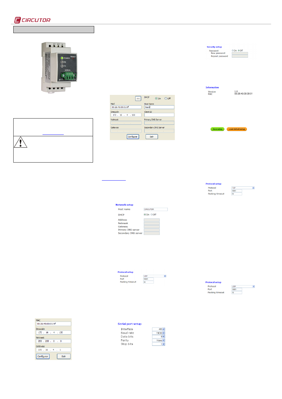
TCP2RS+
The
TCP2RS+ is a communications gateway used to
convert the physical Ethernet environment to serial
RS-485 or RS-232 communications or vice versa in
the routing mode.
This document provides the instructions for use and describes
the operation of the TCP2RS + device. You can download the
manual from CIRCUTOR's web site in case it is misplaced:
Before performing any maintenance operations,
connection modifications, repairs, etc., you must
disconnect the unit from the power supply. If you
suspect an operational fault in the unit or in its
protection system, remove the unit from service. The design of
the unit makes it easy to replace in the event of a fault.
1.- DESCRIPTION
The purpose of the
TCP2RS+ device is to convert the
physical series environment to Ethernet
communications with TCP/IP communication
packets. The gateway is responsible for the
transparent conversion under TCP or UDP
connections. The operation is determined by the
parameterisation carried out in the internal
configuration web menu.
2.- COMMUNICATION
The device is equipped with a self-detecting 10BaseT
/ 100Base TX connection for the physical connection
of the
TCP2RS+ converter to an Ethernet network.
For its configuration has an internal web site from
which the user can define the network protocol used
to communicate with the management software or
communications system master.
2.1.- Ethernet addressing
The device is connected to the master
communication system by means of an IP
connection, and the addressing parameters must be
configured. The configuration modes include the
assignment of a fixed IP or configuration of a DHCP
name.
2.1.1.- Ethernet address assignment
To configure the IP address configuration in any of
the available formats, run program
IPSetup.exe,
supplied with the equipment.
2.1.2.- Fixed IP assignment
To assign the fixed IP address, enter the MAC
address shown on the permanent side label attached
to the device, the format of which is
00:26:45:XX:XX:XX.
In the Address field, enter the IP address being
configured; do the same with the (Netmask) and the
(Gateway) port if necessary. After entering the device
settings, press “Setup” to send the configuration to
the equipment.
2.1.3.- DHCP IP assignment
To assign the DHCP name, choose this option using
the arrow on the upper right, and select On. Once the
configuration fields have been enabled, enter the
MAC
address that can be seen on the permanent side
label attached to the device, the format of which is
00:26:45:XX:XX:XX. In the Address field, enter an
unused, temporary IP address, which is within the
working range of your computer. In the Host Name
field, enter the DHCP name to be assigned to the
equipment. Optionally, the user can configure the
parameters of the ClientID field. The default VendorID
of the device is CIRCUTOR.
2.2.- Configuration web site
After connecting to the Local Area Network (LAN),
and configuring the IP address or the DHCP name,
the device has an internal web site where all the
parameters related to the network protocol and
configuration of the serial port can be configured. To
access the web site, simply use a conventional
Internet browser and enter the IP address or the
name assigned to the device (for example .
2.2.1.- IP address or DHCP name
The internal web site can be used by the user to
apply changes to the DHCP name or to the IP
address previously assigned to the device.
2.2.2.- Network protocol
The device can be connected to the master
communications system by means of three types of
network protocols and to a configurable port (TCP,
UDP or Modbus/TCP). In the case of the
Modbus/TCP protocol, port modification will be
disabled and fixed at 502.
2.2.3.- Configuration of the Serial port
The communications bus parameters can be fully
configured in terms of type of serial Interface (RS-
485/RS-232), transmission speed (from 4800 bps to
115.2 kbps), data bits (7 or 8), parity (no parity, odd
or even) and stop bit (1 or 2). The data will be
configured by default to 8 by selecting the
Modbus/TCP communications protocol.
2.2.4.- Configuration of the setup password
Password can be activated to enable the edition
password. In case to use, the access user is "admin"
and the setup password introduced.
2.2.5.- Device information
The lower part of the screen shows the firmware
version and the machine address of the device (the
same address as that shown on the permanent side
label).
2.2.6.- Save changes
Once any change has been made to the
aforementioned sections, the information must be
saved using the “Save Setup” option. If you wish to
return to the default configuration, select “Load
default setup”.
2.3.- Configuration of network protocols
2.3.1.- TCP Protocol
In the protocol stacCP is the intermediate
layer between t(IP) and the
n general, applications need reliable
communications. The IP layer offers an unreliable
datagram service (no confirmation), so the TCP adds
the functions required to offer a secure, error-free and
zero loss service for the communications between
two systems.
- Protocol: TCP Mode
- Port: Destination TCP Port Lumber
*In any case you can configure the port 80, so is the
web configuration port
- Packing timeout: maximum waiting time
2.3.2.- UDP Protocol
The User Datagram Protocol (UDP) is a message-
oriented minimumprotocol that has
been documented in t t
In tDP provides a simple
interface between tand the
UDP does not offer guarantees
during the delivery of its messages and the UDP
origin does not withhold the states of UDP messages
sent to the network. UDP only adds t
functionality to tand t
of the header and useful load. Any type of
guarantees for the transmission of information must
be implemented in higher layers.
- Protocol: UDP Mode
- Port: Destination UDP Port Lumber
*In any case you can configure the port 80, so is the
web configuration port
- Packing timeout: maximum waiting time
2.3.3.- Modbus/TCP Protocol
Modbus/TCP is a variation or extension of the
Modbus® protocol, which enables it to be used on
the TCP/IP transport layer. Therefore, Modbus/TCP
can be used throughout the Local Area Network or
the Internet. This was one of the objectives that
motivated its development (the specification of the
protocol was submitted to the IETF (Internet
Engineering Task Force).
Document Outline
- 1.- DESCRIPTION
- 2.- COMMUNICATION
- 2.1.- Ethernet addressing
- The device is connected to the master communication system by means of an IP connection, and the addressing parameters must be configured. The configuration modes include the assignment of a fixed IP or configuration of a DHCP name.
- 2.1.1.- Ethernet address assignment
- To configure the IP address configuration in any of the available formats, run program IPSetup.exe, supplied with the equipment.
- 2.1.2.- Fixed IP assignment
- 2.1.3.- DHCP IP assignment
- 2.2.- Configuration web site
- 2.3.- Configuration of network protocols
- 2.1.- Ethernet addressing
- 3.- TECHNICAL SPECIFICATIONS
- 4.- CONNECTIONS
- 5.- TECHNICAL SERVICE