Interpretation of the settings made by plug & play – CIRCUTOR computer PLUS-TF Series User Manual
Page 35
35
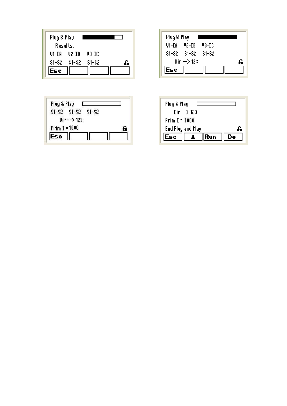
Fig.37.- Plug&Play. Phase allocation information
Fig.38.- Plug&Play. Phase allocation information
Fig.39.- Plug&Play. Secondary sense phase
sequence and primary current transformers
information
Fig.40.- End of Plug&Play
7.2.4
Interpretation of the settings made by Plug & Play
The screen shown on Fig.37 shows information about the phase to which the current transformers have
been connected (CT). If IA, IB and IC are shown together with V1, V2, V3 and all are in the S1-S2 order,
each CT is connected to the correct phase and in the correct direction. However, if you have the
example shown on Fig. 38, this would mean that the current in phase C has been connected instead of B
and vice versa, and phase 3 secondary terminals of the CT have been inverted.
NOTE: This information is usually correct if the load is inductive or slightly capacitive during the
Plug&Play setting (cos fi between 0.65 inductive and 0.98 capacitive). In any case, if you consider that
the connections are correct, you can repeat the Plug&Play setting and if the results are the same, there
is a high probability that the connections are as detected by the automatic setting unit.
The screen on Fig. 39 shows information about the phase sequence connected to V1, V2 and V3 and
about the current transformer ratio, both detected by the Plug & Play automatic setting system.
The final automatic setting is shown on the screen displayed on Fig. 40, indicating the end of the
Plug&Play.