CIRCUTOR computer PLUS-TF Series User Manual
Page 61
61
The options will be selected from the list shown on Fig. 108 with the dynamic keys
. Press
OK when the option selected appears on the reverse video.
Options
Comments
Measurable parameters
Harmonics V1
Shows the voltage harmonics of phase 1
Harmonics V2
Shows the voltage harmonics of phase 2
Harmonics V3
Shows the voltage harmonics of phase 3
Harmonics I1
Shows the current harmonics of phase 1
Harmonics I2
Shows the current harmonics of phase 2
Harmonics I3
Shows the current harmonics of phase 3
Harmonics IC1
Available only in Computer
plus TF-CDI.
Shows the current harmonics of phase 1 of the capacitor bank
Harmonics IC2
Shows the current harmonics of phase 2 of the capacitor bank
Harmonics IC3
Shows the current harmonics of phase 3 of the capacitor bank
THDV
Shows the THD voltage of each phase-neutral voltage: V1, V2, V3
THDI
Shows the THD current of each phase-neutral voltage: I1, I2, I3
THDIC
Only available in Computer
plus TF-CDI.
Shows the THD current of each current in the compensation unit:
IC1, IC2, IC3
Table 11-1.- Options of the harmonics display menu.
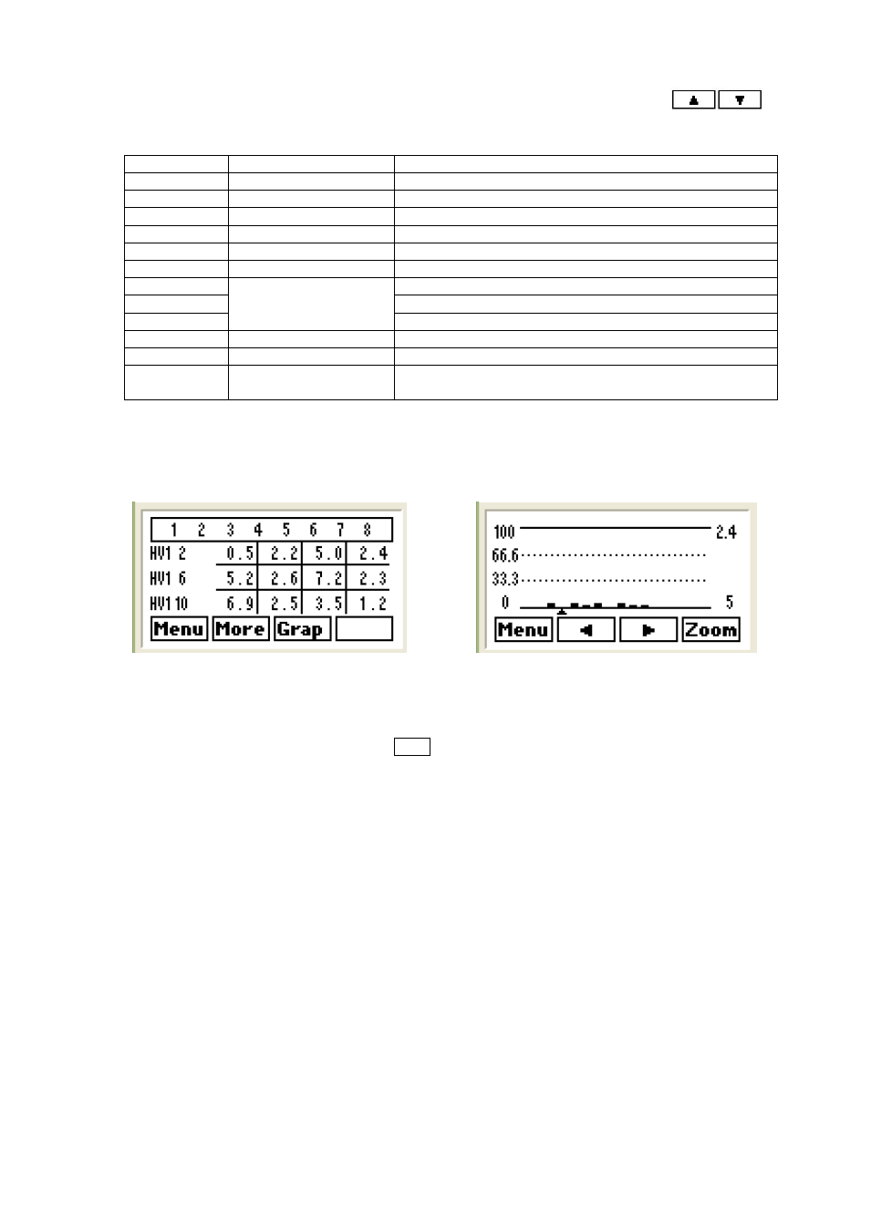
Numerical values or bar graphs can be displayed for each variable (see Fig. 109 and 110).
Fig. 109.- Numerical display of harmonics
Fig. 110.- Graphical display of harmonics
Each numerical harmonics display screen shows a table with the value of 12 harmonics (example on
Fig.109, row HV1 2 shows the voltage harmonic values of phase 1, of the order of 2 to 5. The next row
shows the order from 6 to 9, etc.). Press More to see up to the harmonics order 33.