Mpm-81, Specifications – Oxmoor MPM-81 User Manual
Page 2
Oxmoor Corporation, LLC, 309 Cahaba Valley Parkway, Birmingham, AL 35124 USA Toll Free: 1-800-262-6898
Phone: 205-982-8200 Fax: 205-982-8250 E-mail: [email protected] Internet: www.oxmoor.com
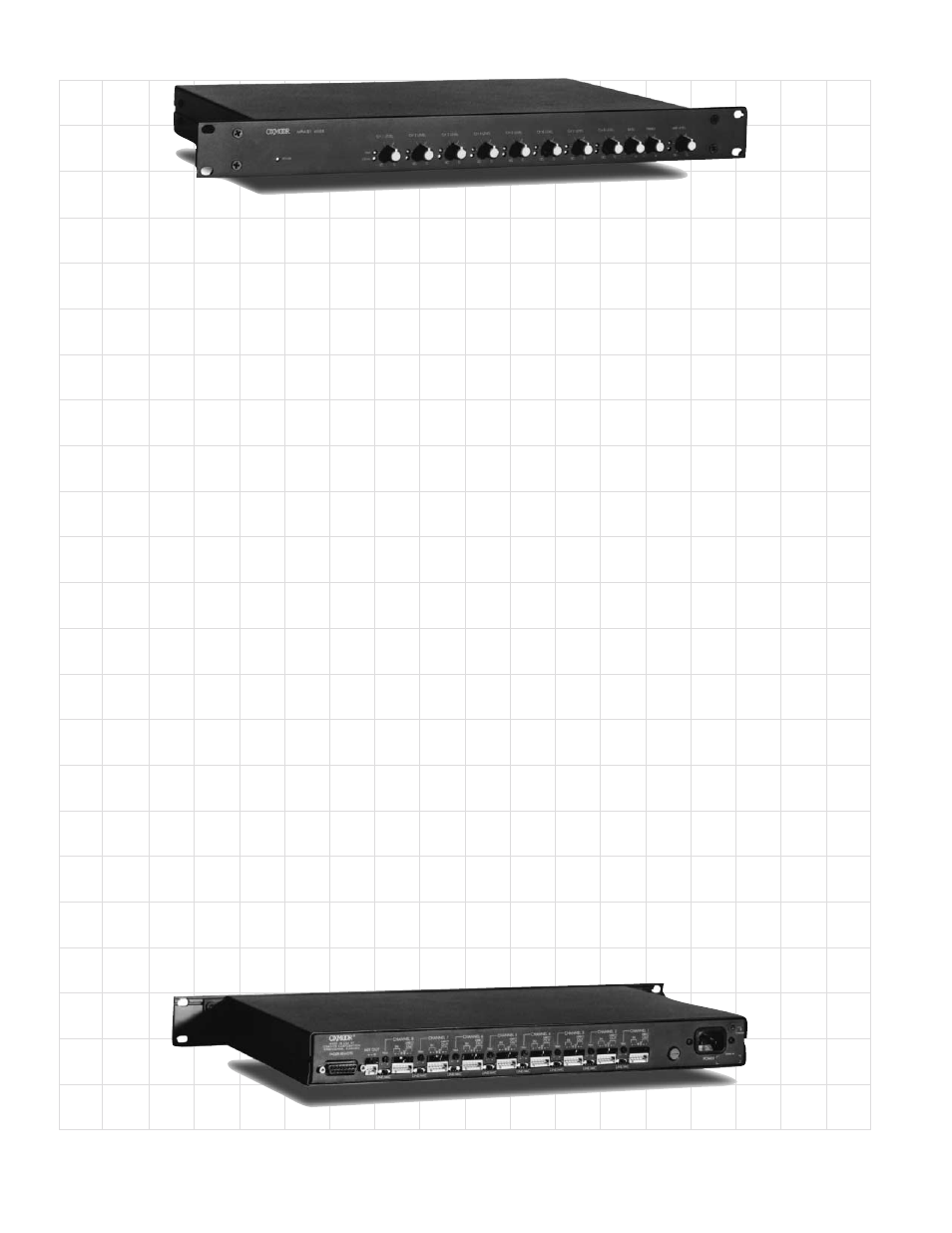
MPM-81
™
SPECIFICATIONS
Specifications subject to change without notice. *SMPTE Method; 60 Hz +7 kHz mixed 4:1.
REV: 1.4 - 8/01
FREQUENCY RESPONSE
FREQUENCY RESPONSE
FREQUENCY RESPONSE
FREQUENCY RESPONSE
FREQUENCY RESPONSE
20 Hz to 20 kHz ...................................................................... +0, -0.3 dB (Ref. +4 dBu)
HUM AND NOISE
HUM AND NOISE
HUM AND NOISE
HUM AND NOISE
HUM AND NOISE
Ref. +4 dB, Input Terminated With 150 ohms,
Output @ Unity Gain (20 Hz to 20 kHz, Unweighted)
Line Input, Direct Output ....................................................... -93 dBu
Microphone Input, Direct Output .......................................... -85 dBu
Line Input, Mix Output ............................................................ -84 dBu
Microphone Input, Mix Output ............................................... -80 dBu
DISTORTION
DISTORTION
DISTORTION
DISTORTION
DISTORTION
THD + Noise and IMD*, Ref. 0 dB, Output @ Unity Gain
Line Input, Direct Output ....................................................... .01%
Microphone Input, Direct Output .......................................... .01%
Line Input, Mix Output ............................................................ .035%
Microphone Input, Mix Output ............................................... .035%
OFF ISOLATION
OFF ISOLATION
OFF ISOLATION
OFF ISOLATION
OFF ISOLATION
Line Input Ref. 0 dBu ............................................................. 80 dB
Microphone Input Ref. -40 dBu ............................................. 80 dB
CROSSTALK
CROSSTALK
CROSSTALK
CROSSTALK
CROSSTALK
Unity Gain, Ref. +4 dB output
Channel to Channel ................................................................ -80 dB (20 Hz to 20 kHz)
MIC/LINE INPUTS
MIC/LINE INPUTS
MIC/LINE INPUTS
MIC/LINE INPUTS
MIC/LINE INPUTS
Type ........................................................................................... Electronically Balanced (RF Suppressed)
Connectors ............................................................................... Cage Clamps with Mating Connector
Input Impedance ..................................................................... 10 K Ohms
Line Input Sensitivity .............................................................. Typical +4 dBu, Maximum +18 dBu
Microphone Input Sensitivity ................................................. Typical -40 dBu, Maximum -22 dBu
Mic/Line Switch ....................................................................... Sets Input for Microphone or Line-Level Source
Mic/Line Trim Control Range ................................................
±
15 dB (Ref. 0 dBu Output)
PROGRAM OUTPUTS
PROGRAM OUTPUTS
PROGRAM OUTPUTS
PROGRAM OUTPUTS
PROGRAM OUTPUTS
Type ........................................................................................... Electronically Balanced (RF Suppressed)
Connectors ............................................................................... Cage Clamps with Mating Connector
Source Impedance .................................................................. 150 Ohms (75 Ohms/Side)
Recommended Load Impedance ........................................... 600 Ohms or Greater
Maximum Output Level ........................................................... Ref. 1 kHz @ Rated THD
Terminated w/600 Ohms .................................................... +24 dBm (All Outputs Driven Simultaneously)
Unterminated ......................................................................... +26 dBu
TONE CONTROLS
TONE CONTROLS
TONE CONTROLS
TONE CONTROLS
TONE CONTROLS
Hi-Frequency ............................................................................ 8 KHz,
±
12 boost/cut
Low-Frequency ......................................................................... 150 Hz,
±
12 boost/cut
DUCK ATTENUATION
DUCK ATTENUATION
DUCK ATTENUATION
DUCK ATTENUATION
DUCK ATTENUATION
Fixed .......................................................................................... -80 dBu
CONTROL PORT
CONTROL PORT
CONTROL PORT
CONTROL PORT
CONTROL PORT
Connector ................................................................................. 25-pin D-sub, Female
VCA Control .............................................................................. +15 VDC “OFF” to 0 VDC “Full ON”
Slope ......................................................................................... 1 dB/65 mV
MIX CONTROL
MIX CONTROL
MIX CONTROL
MIX CONTROL
MIX CONTROL
Connectors ............................................................................... Cage Clamps with Mating Connector
Logic Action .............................................................................. Maintained Closure to Common
Logic Levels ............................................................................. Low < .8 Volts, High > 2.4 Volts
Maximum Sink Current ........................................................... 1 mA
Maximum Cable Length .......................................................... 600 m (2000 ft.), #22 AWG
Switching Time ........................................................................ 50 ms
MAINS POWER
MAINS POWER
MAINS POWER
MAINS POWER
MAINS POWER
Power Requirements ............................................................... 100 to 125 VAC or 200 to 230 VAC, 50/60 Hz
MECHANICAL
MECHANICAL
MECHANICAL
MECHANICAL
MECHANICAL
Overall Dimensions ................................................................. 44mm H x 482mm W x 254mm D
(1.72” H x 19” W x 10” D)
Finish ........................................................................................ Textured Black Paint
Weight ....................................................................................... Shipping: 6.3 Kg (14 lb.)
Net: 5.9 Kg (13 lb.)