Artel DLT710 User Manual
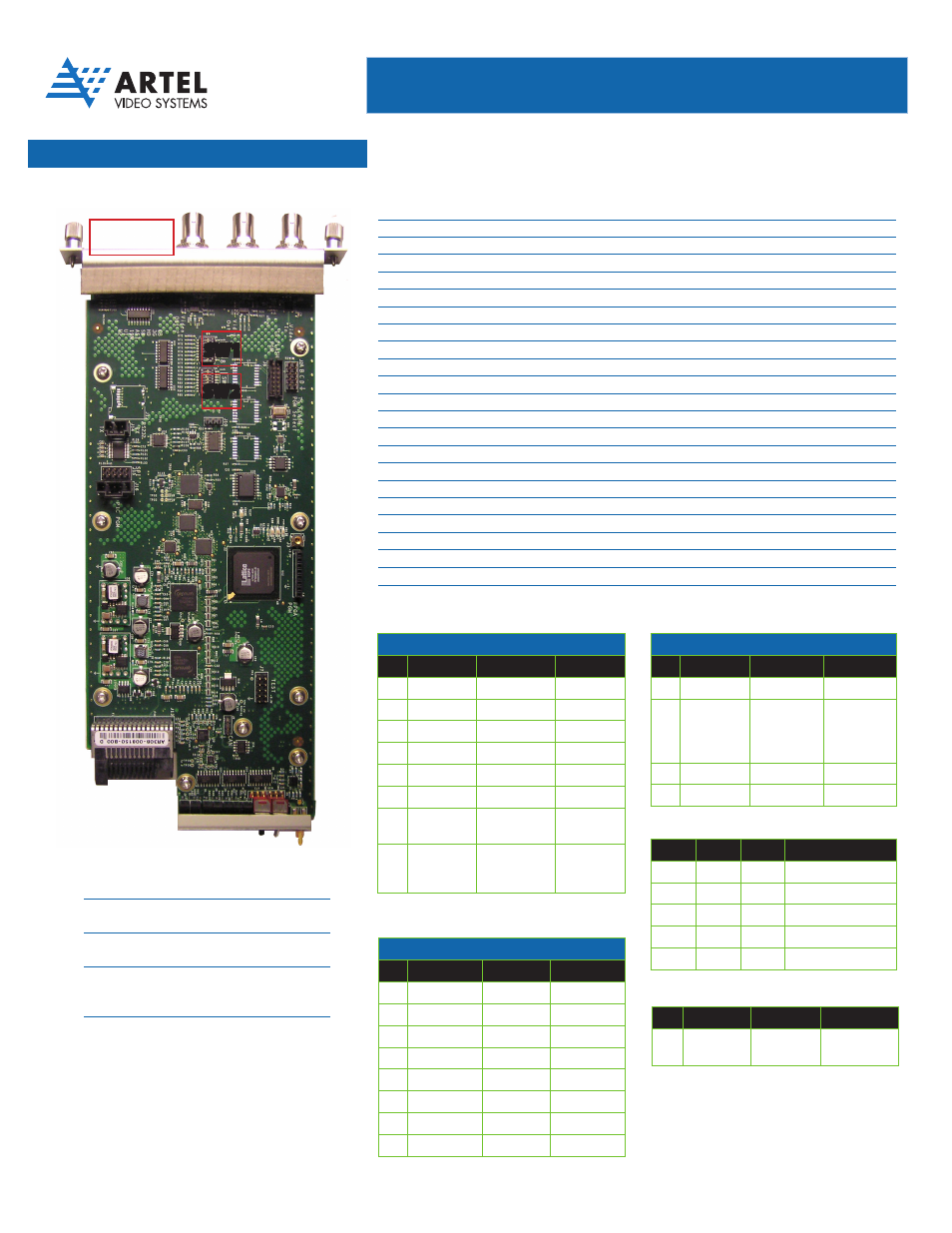
Digilink, Artel ships the dlt710 configured as follows, Dip switch configurations
Simplifying Media Transport
™
DigiLink
Media Transport Simplified
QUICK START GUIDE
Artel ships the DLT710 configured as follows:
• All signal types enabled (3G, HD, SD, DVB-ASI, ATSC)
• Electrical input set to BNC
• Front panel GEN/CHK switch set to CHK
•
LEDS indicate checker status
•
Monitor jack contains copy of input BNC
• Multi-format, continuous test mode enabled
• Signal check test interval set to 60 seconds
• Signal check synchronization interval set to 5 seconds
• SDI generator pattern set to color bars, full screen @ 75%
•
1080p 59.94 frames/sec
•
1080i 29.97 frames/sec
•
525i 29.97 frames/sec
•
Embedded audio is 1 kHz tone @ -20 dBfs, all 4 channels of audio group 1
• DVB-ASI and ATSC generator transport stream
•
SMPTE color bars with moving block
•
MPEG-2 single program @ 19.292 Mb/s
•
SD video format, 720x480i, 29.97 fps
•
Embedded audio is left/right channel, 1 kHz tone @ -20 dBfs, AC-3 format
• Report data rate frequency errors > 40 ppm
• Report inverted DVB-ASI format
• EMS override is allowed (DigiLink Manager can change the DLT710 configuration)
S5
S6
S7
Checker Input
On
On
On
BNC In
Off
Off
Off
Backplane 1
Off
On
Off
Backplane 2
Off
Off
On
Backplane 3
Off
On
On
Backplane 4
Factory Default: All On
DIP Switch Configurations
SW
Function
Off
On
S8
EMS
Override
Local
Remote
Factory Default: All On
SW2 CONFIGURATION
SW
Function
Off
On
S1
HD Vert Res
720p
1080i
S2
Format
625 Line (SD)
50 Field
(HD/3G)
525 Line
(SD)
59.94 Field
(HD/3G)
S3
Reserved
-
Default
S4
Reserved
-
Default
Factory Default: All On
SW1 CONFIGURATION
SW Function
Off
On
S1
Reserved
-
Default
S2
Reserved
-
Default
S3
Reserved
-
Default
S4
Reserved
-
Default
S5
Reserved
-
Default
S6
ASI INV Test
Disabled
Enabled
S7
Freq Test
Disabled
Enabled
S8
Sync Interval
Custom
Normal
Factory Default: All On
SW1
REAR PANEL SWITCHES
SW
Function
Off (Down)
On (Up)
S1
SDI Pattern
Pathological
Color Bars
S2
3G-SDI
Disabled
Enabled
S3
HD-SDI
Disabled
Enabled
S4
SD-SDI
Disabled
Enabled
S5
ASI
Disabled
Enabled
S6
ATSC
Disabled
Enabled
S7
Check Mode
Single-Pass
Test
Continuous
Test
S8
Signal
Test Inter-
val
Custom
Normal
Factory Default: All On
Monitor Mode: All Off (See User Manual for Details)
SW2
SW1
Determines a portion of the test
timing and enables test features
SW2
Determines signal format, input
source, and EMS functionality
Determines test pattern type, signal
type, test mode (continuous or single
pass), and length of test
Configuration Switch Functions
Rear
Panel
Switch
REAR PANEL
SWITCH LOCATION
Multi-Format Digital Video Generator and Test Module
[DLT710]