Using sensor functions with sewing stitch, Sensor function area, B-66 – Baby Lock Crescendo (BLCR) Instruction and Reference Guide User Manual
Page 68
USING SENSOR FUNCTIONS WITH SEWING STITCH
B-66
Before using the sensor functions, carefully read “Utility Stitches” chapter to familiarize yourself with the
machine operations.
The sensor functions are performed using the sensor pen.
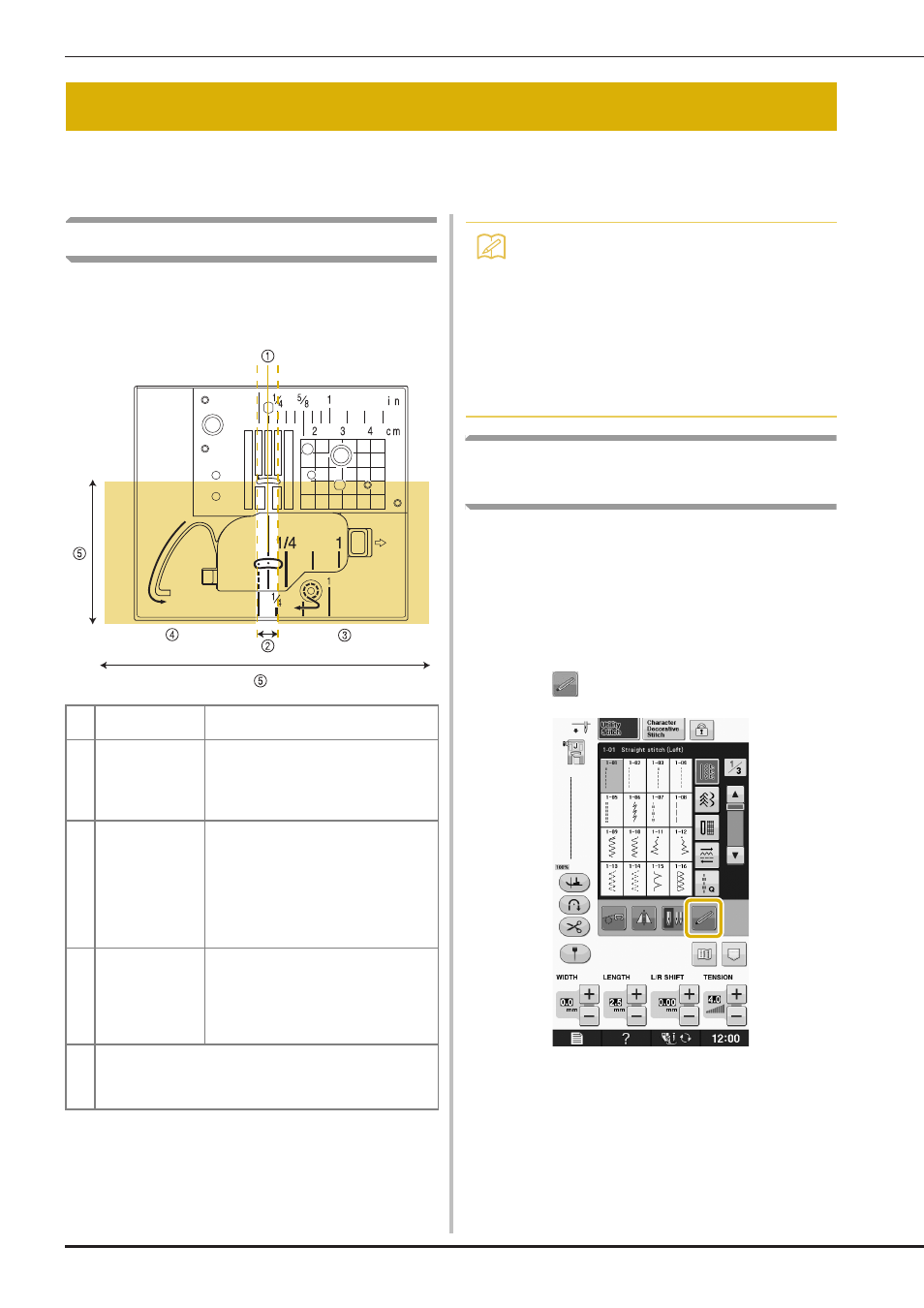
Sensor Function Area
When using the sensor pen with utility stitches, the
operations may differ depending on the area to be
touched.
Specifying the Guideline Marker
Position With the Sensor Pen
The sewing position will be indicated by a red
guideline marker.
The position of the guideline marker can be
adjusted to your desired location.
a
Turn on the machine.
b
Press .
→ The sensor functions screen appears.
USING SENSOR FUNCTIONS WITH SEWING STITCH
a
Center needle
position
Sewing position for stitch patterns sewn
with the center needle position
b
Setting area
Area 3.5 mm to the left and right of a.
Touch this area with the sensor pen to
specify a position.
Area 7 mm, when positioning the
guideline marker.
c
Adjustment area
(right)
Touch: With each touch, the setting
increases by 0.5 mm. This allows fine
adjustments to be made after touching
within b to specify a position.
Long touch: After touching b to specify
a position or adjusting the position by
touching within c or d, long touch to
apply the setting.
d
Adjustment area
(left)
Touch: With each touch, the setting
decreases by 0.5 mm. This allows fine
adjustments to be made after touching
within b to specify a position.
Long touch: Apply the setting in the
same way as a long touch within c.
e
The sensor pen touch range extends approximately 200 mm
(7-7/8 inches) toward you from the needle drop point and 130
mm (approx. 5 inches) to either side of the middle (center)
needle position.
Memo
• There is a narrow space between the setting
area and the adjustment area, when
touched will allow the setting to be changed
to the maximum increased or decreased
setting.
• The borderline areas are respectively 6.5
mm (approx. 1/4 inch) wide when
positioning the guideline marker, and 10
mm (approx. 3/8 inch) wide in other cases.