Contemporary Control Systems BACnet Cube I/O BMT-DIO4/2 User Manual
Digital i/o module bmt-dio4/2
2. Declaration of Conformity
The device was tested according to the applicable standards. Con-
formity was proofed. The declaration of conformity is available at
the manufacturer METZ CONNECT GmbH.
Notes Regarding Device Description
These instructions include indications for use and mounting of the
device. In case of questions that cannot be answered with these
instructions please consult supplier or manufacturer.
The indicated installation directions or rules are applicable to the
Federal Republic of Germany. If the device is used in other countries
it applies to the equipment installer or the user to meet the national
directions.
Safety Instructions
Keep the applicable directions for industrial safety and prevention
of accidents as well as the VDE rules.
Technicians and/or installers are informed that they have to
electrically discharge themselves as prescribed before installation or
maintenance of the devices.
Only qualified personnel shall do mounting and installation work
with the devices, see section “qualified personnel”.
The information of these instructions have to be read and under-
stood by every person using this device.
Symbols
Warning of dangerous electrical voltage
Danger
means that non-observance may cause risk of life,
grievous bodily harm or heavy material damage.
Qualified Personnel
Qualified personnel in the sense of these instructions are persons
who are well versed in the use and installation of such devices and
whose professional qualification meets the requirements of their
work.
This includes for example:
• Qualification to connect the device according to the VDE
specifications and the local regulations and a qualification to put
this device into operation, to power it down or to activate it by
respecting the internal directions.
• Knowledge of safety rules.
• Knowledge about application and use of the device within the
equipment system etc.
3. Technical Data
BACnet Interface
Protocoll
BACnet MS/TP
Transmission rate
9600 ... 115200 Bd
(factory setting 9600 Bd)
Cabling
RS485 two wire bus with voltage
equalizing cable in bus / line topology;
terminate with 120 Ohms
Supply
Operating voltage range
20 ... 28 V AC/DC (SELV)
Current consumption
200 mA (AC) / 75 mA (DC)
Relative duty cycle
100 %
Input
Voltage input
30 V AC/DC
High-signal recognition
>7 V AC/DC
Output
Output contacts
2 changeover contacts
Switching voltage max.
250 V AC
Continuous current max.
16 A / relay (80 A / 20 ms)
Total current for
all contacts
25 A
Housing
Dimensions WxHxD
2.0 x 2.8 x 3.0 in. (50 x 70 x 75 mm)
Weight
126 g
Mounting position
any
Mounting
standard rail TH35 per IEC 60715
Mounting in series
the maximum quantity of modules
without space
connected in line is limited to 15 or
to a maximum power consumption of
2 Amps (AC or DC) per connection to
the power supply. For any similar
block of additional modules a sepa-
rate connection to the power supply
is mandatory.
Material
Housing
Polyamide 6.6 V0
Terminal blocks
Polyamide 6.6 V0
Cover plate
Polycarbonate
Type of protection
(IEC 60529)
Housing
IP40
Terminal blocks
IP20
Terminal blocks
Supply and bus
4 pole terminal block
max. AWG 16 (1,5 mm²) solid wireg
max. AWG 18 (1,0 mm²) stranded wire
Wire diameter
min. 0.3 mm up to max. 1.4 mm
(terminal block and jumper plug are
included to each packing unit)
Module connection
Input/Output
max. AWG 12 (4.0 mm²) solid wire
max. AWG 14 (2.5 mm²) stranded wire
Wire diameter
min. 0.3 mm up to max 2.7 mm
Protective circuitry
polarity reversal protection of
operating voltage
polarity reversal protection of supply
and bus
Temperature range
Operation
-5 °C ... +55 °C
Storage
-20 °C ... +70 °C
Display
Operating / bus activity
green LED
Error indication
red LED
Status of the
inputs & outputs
yellow LED
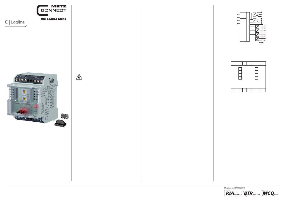
5. Connection Diagram
4
3 C1 C1
22 21 24
BUS A-
BUS B+
A1
A2
A-
B+
A1
A2
A-
B+
GND
24 V AC/DC
1
2 C1 C1
12 11 14
4. Wiring Diagram
BUS A-
BUS B+
12 N.C.
11 C
A2 /GND
A1/+24 V
BACnet MS/TP on RS-485
RISC - CPU
24 V
14 N.O.
22 N.C.
21 C
24 N.O.
1
2
C1
3
C1
4
C1
C1
GND
+24 V
J
7624/899299-04
Digital I/O Module
BMT-DIO4/2
1108831326
1. Description
The BACnet MS/TP module with 4 digital inputs and 2 relay
outputs with manual control was developed for decentralized
switching tasks. It is suitable for accommodating, for example,
light switches and window contacts in a room, switching two light
strips or controlling louvers. It can also be used to control 2 mo-
torized fire dampers. With strong inductive loads, we recommend
protecting the relay contacts with an RC element. The inputs can
be used as contact or voltage inputs. The inputs and outputs can
be switched and scanned by means of standard objects via a BAC-
net client. The module address and the baud rate are set by means
of two address switches on the front.
Suitable for decentralized mounting in serial sub-distributor.
METZ CONNECT GmbH | Im Tal 2 | 78176 Blumberg | Germany
Phone +49 7702 533-0 | Fax +49 7702 533-433
Mounting instruction see www.metz-connect.com