Crydom AC Output SSRs User Manual
Ac output ssrs, Panel mount, Mounting instructions
Rev. 100711
AC Output SSRs
Panel Mount
This installation sheet includes detailed mounting and wiring instructions which apply for most Crydom Panel
Mount DC output SSRs. Be sure to visit the product series' datasheet available at the Crydom website to
complement this information. If you have questions or need additional information please contact Crydom Tech
Support.
Lug Terminal
Hardware Kit
Cover
TABLE 1. Accessories
Thermal Resistance
[ºC/W]
Heat Sink
Part No.
5.0
3.5
3.0
2.7
2.5
2.0
2.0
1.7
1.5
1.2
1.0
0.7
0.5
HS501DR
HS351 / HS351DR
HS301 / HS301DR
HS271 / HS271DR
HS251
HS202 / HS202DR
HS201 / HS201DR
HS172
HS151 / HS151DR
HS122 / HS122DR
HS103 / HS103DR
HS072
HS053
KS100
HK1
TRM1
TRM6
Thermal Pad
HSP-1
HSP-2
(A)
See compatible accessories in corresponding datasheet.
(B)
Load can be wired to either terminal 1 or terminal 2. Proper polarity must be observed for
the DC control power supply with terminal 3 being positive with respect to terminal 4.
(C)
Not compatible with some applications. For details contact Crydom Technical Support.
MOUNTING INSTRUCTIONS
Mounting on Heat Sink
Mounting on Panel
Choose one of the two mounting options and follow the instructions.
Locate the panel section on which the SSR will be mounted. Panel mount surface must provide
adequate heat sinking capability, uncoated, clean, flat and preferably aluminum.
Be sure to use a thermal pad or thermal compound between the SSR and the panel.
SSR mounting slots have a diameter of 0.2 in (5.0 mm). Two screws are needed (not included) to mount
the SSR onto panel. Choose screw length considering the mounting surface and that the SSR baseplate
thickness is 0.125 in (3.2 mm).
Before applying full torque tighten down both screws until they contact the baseplate. Then, tighten
them to 20 in-lbs (2.2 Nm).
Select adequate heat sink (see thermal derating curves in product series’
datasheet).
Be sure to use a thermal pad or thermal compound between the SSR and the
selected heat sink.
SSR mounting slots have a diameter of 0.2 in (5.0 mm). Two screws are
needed to mount the SSR onto heat sink (See fig. 1). Mounting screws are
sold separately as HK1 and are suitable for all Crydom heat sinks. Otherwise,
recommended screw size is 8-32 (UNC standard) or M4 (metric). Choose
screw length considering the mounting surface and that SSR baseplate
thickness is 0.125 in (3.2 mm).
fig. 1
SSR mounted
on HS053 heat sink
(A)
(A)
Before applying full torque tighten down both screws until they contact the baseplate. Then, tighten
them to 20 in-lbs (2.2 Nm).
For optimal thermal performance heat sink fins should be oriented vertically to promote natural
convection airflow.
(B)
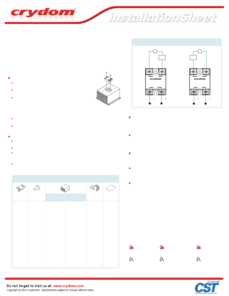
WIRING DIAGRAMS
Wire Size
Maximum wire size capacity per terminal: Input 2 x 12 AWG (3.3 mm
2
), output 2 x 8 AWG
(8.4 mm
2
). Choose wire gauge according to actual load current. For larger wire sizes use
lug terminals (see TABLE 1 for available part numbers).
Connections
Ensure that wires ends are stripped to a minimum length of 0.46 in (11.7 mm) for input
and 0.49 in (12.5 mm) for output.
Transient Protection
For applications where transient overvoltage in excess of rated off-state blocking
voltage is likely, a relay with internal overvoltage protection should be selected.
Terminals
Screw type, finger proof (IP20 only). Input: 6-32, Combo Drive. Output: 8-32, Combo
Drive. Maximum screw torque is 10 in-lbs (1.1 Nm) on input and 20 in-lbs (2.2 Nm) on
output.
(A)
AMERICA
Sales Support
Tel.: +1 (877) 502 5500
Tech Support
Tel.: +1 (877) 702 7700
EMEA
Sales Support
Tel.: +44 (0) 1202 606030
Tech Support
ASIA PACIFIC
Sales Support
Tel.: +86 (0) 21 6065 6699
Tech Support
(C)
Please read all mounting instructions before using your AC Output Panel Mount Solid State Relay (SSR).
Important Considerations
Be sure to use input and output voltages within operating ranges.
LED indicates only input status. It does not represent output status.
V
Load
1
4
2
3
S O L I D S T A T E R E L A Y
OUTPUT
INPUT
1 (~)
2 (~)
4 (– / )
3 (+ / )
Load
V
1
4
2
3
S O L I D S T A T E R E L A Y
OUTPUT
INPUT
4 (– / )
3 (+ / )
1 (~)
2 (~)
Generic AC Output SSRs Wiring Diagram
AC
AC