Daktronics SETTING LIMIT SWITCHES User Manual
Setting limit switches
Copyright © 2011 Daktronics, Inc. Page 1 of 1
DD1995254 4 April 2011
SETTING LIMIT SWITCHES
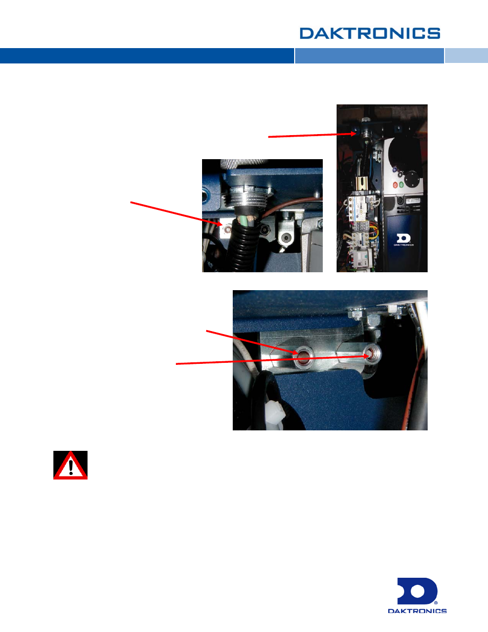
The limit switches are typical for Daktronics Pro Series and
S Series control systems. Access the limit switches by opening
the electrical cover on the offstage end of the hoist.
The limit switch adjusters are two
3/8" Hex Head Nuts located on the
back upper wall of the enclosure. The
nuts are partially hidden by the
electrical wiring.
Use a nut driver to adjust the limits:
Lower Limit switch (left) – rotate the
adjusters counter-clockwise to set
limits to a lower position
Higher Limit switch (located toward the
hoist center) – rotate the
adjuster clockwise to set limits to a
higher position
Do not force the limit switch adjusters or damage may occur to the limit switch assembly
inside the hoist. The upper and lower limit switches are preset at the factory to approximate
settings based on project information.