Fire Magic 3050 Infrared Burnet Kit User Manual
Infrared burner kit instructions, Hot surface ignition), Installation
REV 6 - 1502230915
L-C2-251
1
ROBERT H. PETERSON CO. • 14724 East Proctor Avenue • City of Industry, CA 91746
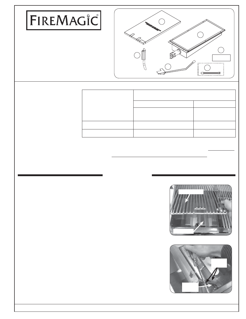
PARTS INCLUDED
1. Infrared burner
2. Electrode assembly
3. Burner cover
4. Label
5. Flash tube
6. Adapter wire*
TOOLS REQUIRED
• Phillips
screwdriver
• Pair of needle-nose pliers
• 1/4 hex nut driver
• 3/8 hex nut driver
INFRARED BURNER KIT
INSTRUCTIONS
(HOT SURFACE IGNITION)
Model # 3050
# 3060
Included parts
6*
5
4
3
2
1
NOTE:
This unit has been retrofi tted
with an infrared burner.
Fig. 1-1 Remove cooking and fl avor grid
REMOVING THE OLD BURNER
1. Be sure the grill is completely cool and the gas is completely
shut off. Open the oven lid.
2. Remove the cooking grid from above the burner by lifting it fi rst
from the front and set it aside (see Fig. 1-1).
3. Remove the fl avor grid from above the burner and set it aside (see
Fig. 1-1). The fl avor grid will not be used with the infrared burner.
4. Remove the fl ash tube by removing the two hex nut screws using
the 1/4 inch hex nut driver; pulling it directly away from the grill fi re
wall and off the mounting pin and the ignitor electrode (see Fig.
1-2). Retain screws for installation.
Cooking grid
Fig. 1-2 Remove the fl ash tube
*
The adapter wire (item #6) is provided for use with Echelon grills
that are equipped with ignitor buttons for lighting. (Push to light
confi gurations do not require this adapter.)
Table 1-1
Infrared Orifi ce Chart
Kit Model # 3050
Kit Model # 3060
Grill Models:
A/E660, A/E790, E1060
Grill Models:
A430, A540
Natural Orifi ce
3001-45
3001-49
Propane (L.P.) Orifi ce
3001-55
3001-56
Flavor grid
Hex nut
screws
Old fl ash
tube
INSTALLATION