Wiring – GAI-Tronics 9974 Junction Box User Manual
Page 3
Pub. 42004-101C
Model 9974 Junction Box
Page:
3 of 4
f:\standard ioms - current release\42004 instr. manuals\42004-101c.doc
11/12
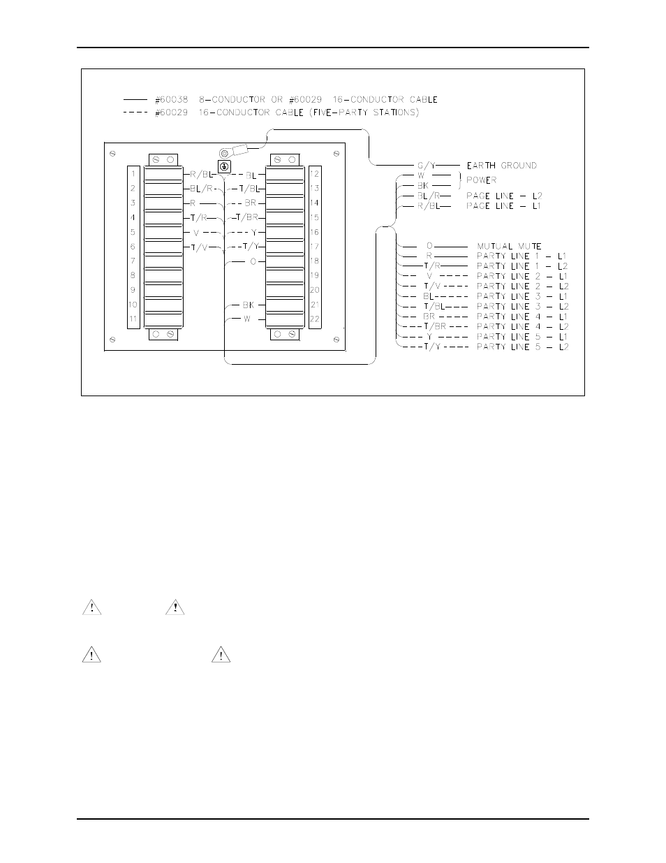
Figure 2. Wiring Diagram (Typical)
Wiring
Figure 2 is the wiring diagram for Model 9974. The wire color code is based on GAI-Tronics 60038 or
60029 inter-station cable, and 60021 speaker cable. Power connections should be made with No. 14
AWG conductors while signal connections should be made with No. 18 AWG conductors. Use of
GAI-Tronics cable, following the correct wire color designations, will ensure that power and signal
connections are made with the proper gauge wire.
N
OTE
:
The installer must crimp a round lug onto the earth ground wire, and bolt it to the ground
stud at the top of the enclosure.
Any single screw terminal is large enough to accept up to two No. 12 AWG conductors.
WARNING
- Explosion hazard - Substitution of components may impair suitability for
Class 1, Division 2.
AVERTISSEMENT
- Risque d’explosion - La substitution de composants peut rendre ce
materiel inacceptable pour les emplacements de Class I, Division 2.
This equipment is suitable for use in Class I, Division 2, Groups A, B, C, and D; Class II, Division 2,
Groups F and G; Class III, Div. 2, or non-hazardous locations only.