Installation, 1 operation control and connectors, Promig 540r control unit – Kemppi Promig 540R User Manual
Page 5
Advertising
4 – Promig 540R, Promig 120R/0425
©
KEMPPI
OY
Promig 540R, Promig 120R/0423 – 5
©
KEMPPI
OY
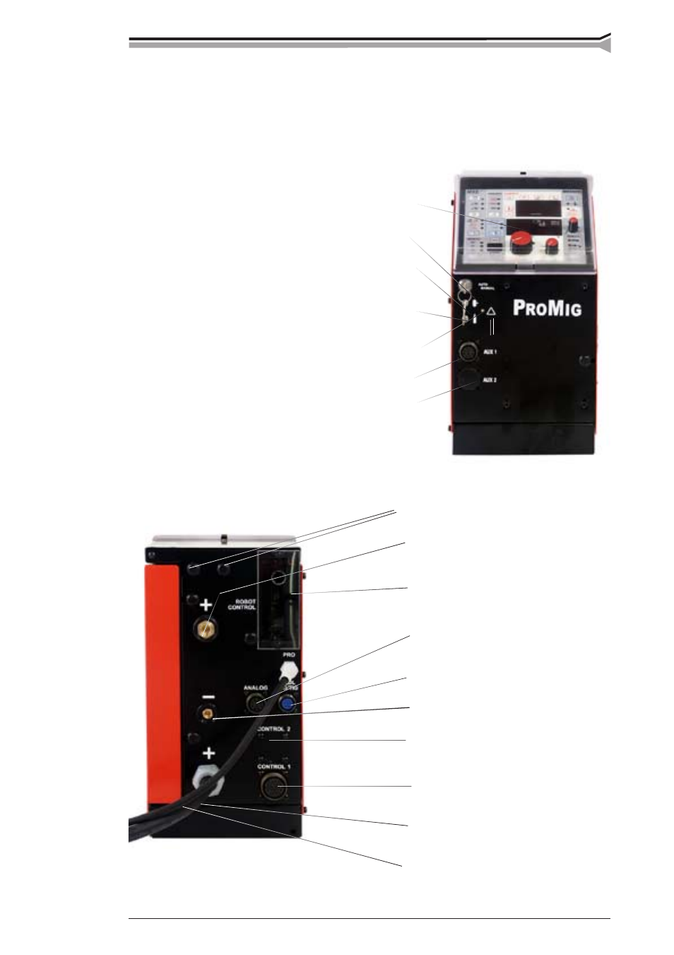
2. INSTALLATION
2.1 OPERATION CONTROL AND CONNECTORS
2.1.1. Promig 540R control unit
MXE control panel
Wire inch
Gas purge
Motor overcurrent indicator
Place for user connector
Holes for gas snap connectors
Welding current output connector (+)
Control cable connector (to 120R or
voltage controlled wire feeder SWF)
Control cable connector (to 2nd 120R)
Robot controller fieldbus
Control cable connector (Probus)
Voltage monitoring connector (–)
Fixed welding cable to Pro power source
Fixed control cable to Pro power source
Lock switch of panel
Signal throughput connector
Analog signal to robot
Advertising
This manual is related to the following products: