Maytag UXT4036AAW Dimension Guide User Manual
Maytag Hoods
18" (45.7 cm)
min. clearance
upper cabinet
to countertop
36" (91.4 cm)
base cabinet
height
13" (33 cm)
cabinet depth
18" (45.7 cm) min.
24" (61.0 cm)
suggested max.
bottom of cabinet
to cooking surface
30" (76.2 cm) or
36" (91.4 cm) min.
cabinet opening width
PRODUCT MODEL NUMBERS
VENTING METHODS
UXT3030AA
UXT3036AA
UXT4030AA
UXT4036AA
●
A 120 Volt, 60 Hz., AC only, 15-amp, fused electrical circuit is
required.
Range Hood – 30" (76.2 cm), 36" (91.4 cm)
Because Whirlpool Corporation policy includes a continuous commitment to improve
our products, we reserve the right to change materials and specifications without notice.
Dimensions are for planning purposes only. For complete details, see Installation
Instructions packed with product. Specifications subject to change without notice.
Ref. W10112419C
2/12/10
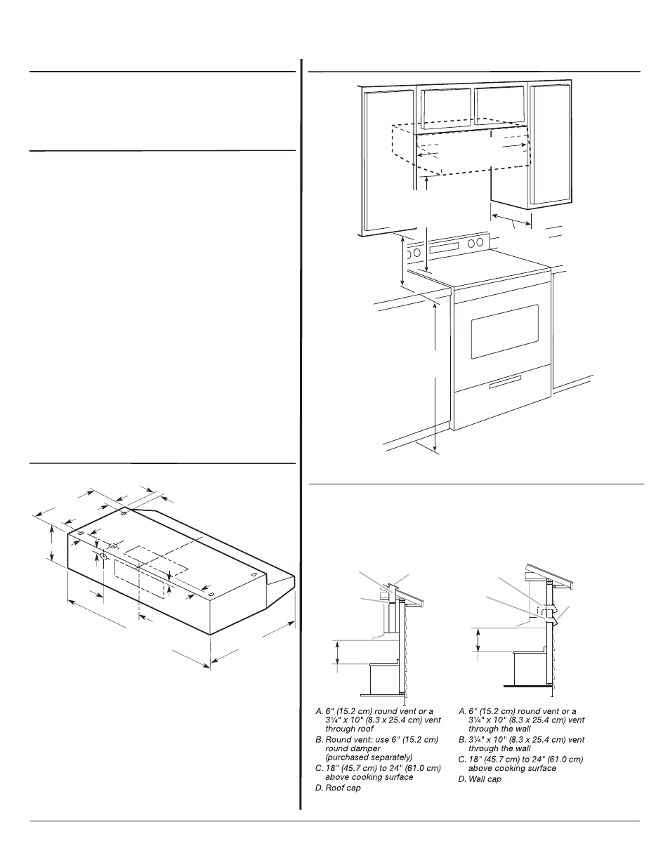
LOCATION REQUIREMENTS
Roof Venting
Wall Venting
A
B
D
C
A
B
C
D
IMPORTANT: Observe all governing codes and ordinances.
●
It is the installer’s responsibility to comply with installation
clearances specified on the model/serial rating plate. The
model/serial rating plate is located inside the range hood on the
rear wall.
●
Range hood location should be away from strong draft areas,
such as windows, doors and strong heating vents.
●
Cabinet opening dimensions that are shown must be used. Given
dimensions provide minimum clearance. Consult the
cooktop/range manufacturer installation instructions before
making any cutouts.
●
Grounded electrical outlet is required. See “Electrical
Requirements” section.
●
All openings in ceiling and wall where range hood will be installed
must be sealed.
For Mobile Home Installations
The installation of this range hood must conform to the
Manufactured Home Construction Safety Standards, Title 24 CFR,
Part 328 (formerly the Federal Standard for Mobile Home
Construction and Safety, title 24, HUD, Part 280) or when such
standard is not applicable, the standard for Manufactured Home
Installation 1982 (Manufactured Home Sites, Communities and
Setups) ANSI A225.1/NFPA 501A*, or latest edition, or with local
codes.
PRODUCT DIMENSIONS
7
¹⁄₂
"
(19.1 cm)
2"
(5.1 cm)
1
¹⁄₂
"
(3.8 cm)
1"
(2.5 cm)
1
¹⁄₂
"
(3.8 cm)
6"
9"
(22.9 cm)
12"
(30.5 cm)
³⁄₄
"
(1.9 cm)
³⁄₈
"
(9.5 mm)
17
¹⁄₂
"
(44.5 cm)
29
⁷⁄₈" (75.9 cm) - 30" (76.2 cm) model
35
⁷⁄₈" (91.1 cm) - 36" (91.4 cm) model
(15.2 cm)
Vent system can terminate either through the roof or wall. Use 3
¹⁄₄" x 10" (8.3 x
25.4 cm) with a maximum recommended vent length of 35 ft (10.7 m) or 6"
(15.2 cm) round vent with a maximum length of 50 ft (15.2 m) for vent system.
NOTE: Flexible vent is not recommended. Flexible vent creates back pressure and
air turbulence that greatly reduce performance.
CABINET DIMENSIONS
Page 1 of 2