Methven Tahi Thermostatic Mixer Valve (2 Outlets) User Manual
Methven For Home
TESTING METHOD -
The valve should be tested to ensure correct operation at
commissioning and thereafter at intervals no greater than 12
months.
Notes:
The testing will only require a normal thermometer with a
●
scale greater than 65°C. The temperature sensitive element of
the thermometer should always be fully inserted into the water
flow.
Temperature readings should be taken at the normal flow rate
●
after allowing for the system to stabilise.
If the Tahi thermostatic mixing valve has been adjusted
●
or serviced it must be re-commissioned and re-tested in
accordance with these instructions.
When commissioning/testing is due the following
performance checks shall be carried out:
Measure the mixed water temperature and record.
1.
The testing will only require a normal thermometer with a
2.
scale greater than 65°C. The temperature sensitive element of
the thermometer should always be fully inserted into the water
flow.
Carry out a cold fail/safe shut-off test by using the isolation
3.
valve to shut off the water to the cold supply.
Wait 5 seconds, if water is still flowing check that the water
4.
temperature is below 46°C. The flow should stop or reduce to
a trickle.
Open cold water isolation valve and measure mixed water
5.
temperature.
Notes:
If there is no significant change to the set outlet temperature
●
(±2°C or less change from the original settings) and the fail-
safe shut off is functioning, then the valve is working correctly
and no further service work is required.
If the outlet temperature has drifted by more than 2°C, or
●
if the fail/safe function does not work, a full service or re-
commissioning is required.
If there is a residual flow during the commissioning or the
●
annual verification (cold water supply isolation test), then this
is acceptable providing the temperature of the water seeping
from the valve is no more than 2°C above the designated
maximum mixed water outlet temperature setting of the valve.
Temperature readings should be taken at the normal flow rate
●
after allowing for the system to stabilise.
The sensing part of the thermometer probe must be fully
●
submerged in the water that is to be tested.
Any TMV that has been adjusted or serviced must be
●
re-commissioned and re-tested in accordance with the
manufacturers’ instructions.
Water Supply (Water Fittings) Regulations 1999
This valve complies with the requirements of the above Regulations
and installation should be carried out in strict compliance with
them.
OPERATING CONDITIONS OF USE -
Before installation the operating conditions of use must be checked. Table
1 contains details of the necessary conditions of operation. If your water
supply cannot meet these conditions then the valve cannot be guaranteed to
operate as a Type 2 valve. This valve is suitable for use in HP (BS 1111) operating
conditions.
Operating pressures above 5.0 Bar will require the installation of a pressure
reducing valve.
Operating Conditions of Use
BS1111
Maximum Static Pressure
10 bar
Flow pressure (Hot & Cold)
0.5 bar – 5 bar*
Hot Supply Temperature
55 - 65 °C
Optimum Hot Supply Temperature
60 - 65 °C
Cold Water Supply Temperature
5 – 25 °C
Pressure Designation of Use
HP* S/BT
Maximum Allowable Outlet Temperature
46 °C
Installation Type
Concealed
Max Dynamic Pressure Ratio
(Hot to Cold OR Cold to Hot)
3.5 : 1
Minimum Temperature Differential Between Either
Supply and Outlet Temperature
12 °C
Table 1. Operating Conditions of use
* If a water supply is fed by gravity then the supply pressure should be verified
to ensure the conditions of use are appropriate for the valve.
RECOMMENDED OUTLET TEMPERATURES -
Bath Fill
44 °C **
Shower
41 °C
The mixed water temperature at the terminal fitting must never exceed
●
46 °C
The maximum mixed water temperature can be 2°C above the
●
recommended maximum set outlet temperatures.
** 46°C is the maximum mixed water temperature from the bath tap. The
maximum temperature takes account of the allowable temperature tolerances
inherent in thermostatic mixing valves and temperature losses in metal baths.
It is not a safe bathing temperature for adults or children.
The British Burns Association recommends 37 to 37.5°C as a comfortable
bathing temperature for children. In premises covered by the Care Standards
Act 2000, the maximum mixed water outlet temperature is 43°C.
TAHI THERMOSTATIC MIXER VALVE INSTALLATION -
The Tahi thermostatic mixer valve is precision engineered and will give
●
continuous safe and controlled performance providing it is installed,
commissioned and maintained according to the instructions contained in
this document.
The valve must be so installed that it is readily accessible for
●
commissioning and maintenance when being installed in accordance with
TMV2.
The valve is fitted with integral “listed” single check valve cartridges
●
which command the water supply; therefore the thermostatic valve is
protected against cross-flow due to unbalanced line pressures as required
by the Water Supply (Water Fittings) Regulations 1999.
The valve must be installed with isolation valves on both the hot and cold
●
water supplies as close as possible to the valve; so as to allow the valve to
be commissioned and tested correctly.
The fitting of strainers is recommended as close as is practicable to the
●
water supply inlets of the thermostatic mixing valve. (Recommended
maximum mesh aperture of 0.02”).
TAHI THERMOSTATIC MIXER VALVE (1 and 2 outlets)
INSTALLATION AND MAINTENANCE INSTRUCTIONS FOR
COMPLIANCE TO THE TMV2 SCHEME
Issue A
435027
Methven warrants this product against manufacturing defects and that it is suitable for use under the operating conditions specified in this
instruction sheet.
For your warranty please refer to www.methven.com or call Customer Service
New Zealand
0800 804 222
Australia
1300 638 483
UK
0800 195 1602
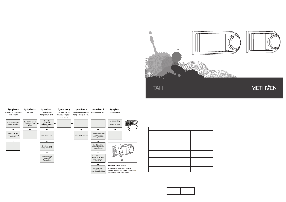
Check non-return
valve function.
Check strainers
around cartridge for
blockage.
Check non-return
valve function.
Check limit
settings (Refer
commissioning).
Check Strainer
around cartridge for
blockage.
7
operate.
screws (A). Screws
tight only
Check installation
depth is within
manufacturers stated
limits (refer step 1)
A.
FAULT FINDING FLOWCHART