MovinCool GX484560-2320 User Manual
Installation manual, Inventory, Fig. 2 fig. 1 2. installation of switch assembly
1. Inventory
After unpacking, please check to make sure you have the correct part number of the
switch assembly. If the switch assembly has incorrect part number or appear damaged,
please contact your MovinCool reseller for replacement (See Fig.1). Please keep this
installation manual with the operation manual for future reference.
1
INSTALLATION MANUAL
For Classic Plus 14 - Serial Number: 1200XXXX140 to 0307XXXX140
Switch Assembly (Part No. GX484560-2320)
Switch Assembly
Fig. 2
Fig. 1
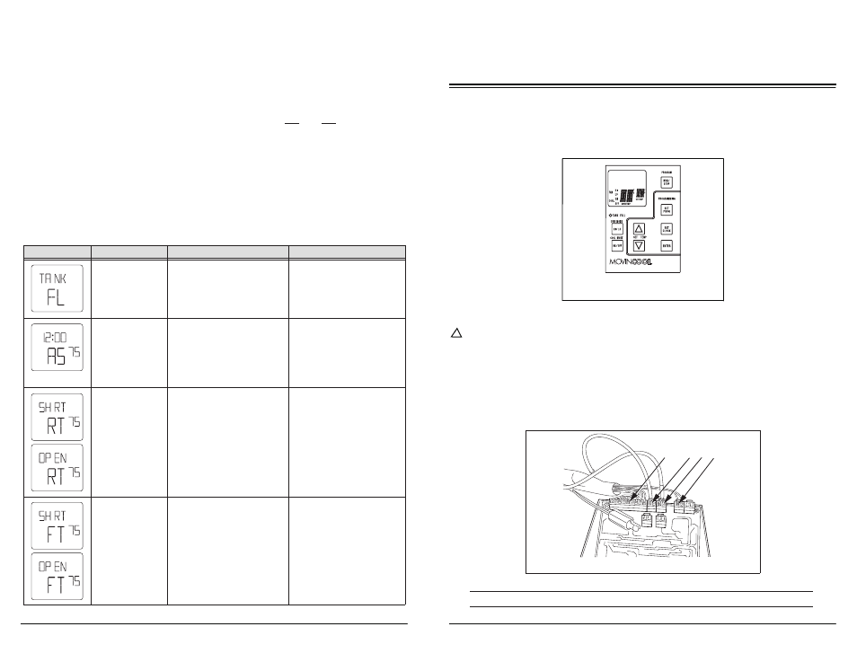
2. Installation of Switch Assembly
WARNING: Disconnect power supply from the unit before performing any
service. Beware that some residual voltages may remain in the
unit immediately after the power is disconnected.
!
2-1. Connect the following connectors to the switch assembly (See Fig. 2):
A. J201 (10-pin) Wire Harness, relay board to the switch assembly.
B. J101 (2-pin) Room Temperature Thermistor.
C. J102 (2-pin) Freeze Protection Thermistor.
D. J103 (2-pin) Drain Tank Switch.
A
B C D
< NOTE >
• Connector J104, J106, and J108 are not used.
Classic Plus 14
Manual P/N: GX484007-3710 First Issue: June 2012
4
4. Self-Diagnostic Codes of Switch Assembly
LCD Display
Description
Condition
Reset/Remedy
Drain tank is full.
When the drain tank is filled
with drain water.
(“TANK FL” LED flashes.)
1) Drain away.
(LCD indicates “TANK”)
Condensate pump
problem
When (optional) condensate
pump is damaged or broken.
1) Fix the condensate pump.
2) Reset the system.
To RESET: Press ON/OFF
and HI/LO buttons on the
control box simultaneously
for 5 seconds.
2) Press ON/OFF button.
Defect (short or
open) of room
thermistor
When room thermistor
(connecting to J101) becomes
short or open.
Disconnect and reconnect
the room thermistor.
If it does not work, then
change it.
Defect (short or
open of freeze
protection
thermistor
When freeze protection
thermistor (connecting to
J102) becomes short or open.
Disconnect and reconnect
the freeze protection
thermistor. If it does not work,
then change it.
TU
AM
F
SET TEMP
HI
ON
COOL
FAN
F
SET TEMP
HI
ON
COOL
FAN
F
SET TEMP
HI
ON
COOL
FAN
F
SET TEMP
HI
ON
COOL
FAN
F
SET TEMP
HI
ON
COOL
FAN
3-4. Operating in FAN ONLY Mode
1.
The unit can also be operated in FAN ONLY mode by pressing FAN HI/LO
button (LCD indicates “FAN HI/LO” and “COOL OFF”).
2.
The unit can then be turned off by pressing the FAN HI/LO button until fan
turns off (FAN ONLY mode speed sequences are HI > LO > OFF).
3-5. Changing from FAN ONLY Mode to COOL Mode
The COOL mode can be activated while the unit is operating in FAN ONLY mode.
To do this, simply press the COOL ON/OFF button (LCD indicates “COOL ON”).
Note: The FAN ONLY mode does not operate after the COOL mode has been
activated. The unit can only be turned off by pressing the COOL ON/OFF button.
3. Operation of Switch Assembly (cont.)