MovinCool 30HU User Manual
Installation manual
1
Fig. 3
Fig. 2
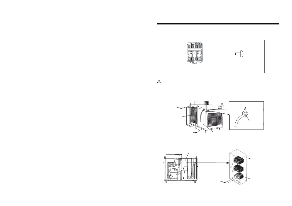
Fig. 1
Sub Control Box
Compressor Relay
Sub Control Box
Manual P/N: 484007-3700 First Issue: May 2012
Compressor Relay (1)
Screw (2)
M4 × 0.7, L=10
Screws (6)
Screws (2)
Left Rear Panel
Left Front Panel
Screws (4)
Compressor Relay (Part No. 484530-0660)
in the unit immediately after the power is disconnected.
Screws (2)
Power Cord
Conduit
1. Inventory
After unpacking, please check to make sure you have the following items. If any of these items
were not included in the box or appear damaged, please contact your MovinCool reseller for
replacement (See Fig.1).
INSTALLATION MANUAL
For 30HU (Classic 40) - Serial Number: 0401XXXX to 0807XXXX
WARNING: Disconnect power supply from the 30HU (Classic 40) unit before
performing any service. Beware that some residual voltages may remain
!
2-1. Remove six (6) screws and take off the left rear panel. Loosen two (2) screws fixing the
2-2. Remove all compressor wires (black) and two (2) screws from the compressor relay
in the sub control box. Then take off the compressor relay.
power cord conduit. Then remove four (4) screws and take off the left front panel.
2. Removal of Old Compressor Relay