Obvius A8923-4 User Manual
Installation, wiring and setup, Modbus point map, Read instructions throughly prior to install
Obvius A8923-4 Installation Instructions
IO Module: Analog 4-20mA/0-10V and Pulse to Modbus
WARNING--REFER INSTALLATION AND SERVICING TO QUALIFIED PERSONNEL ONLY!
●
Read instructions throughly prior to install
●
This product is not intended for life or safety applications
Applications shown are suggested means of installing this product, but it is the responsibility of the installer to ensure that the
installation is in compliance with all national and local codes. Installation should be attempted only by individuals familiar with
proper installation techniques and with codes, standards, and proper safety procedures for control installations.
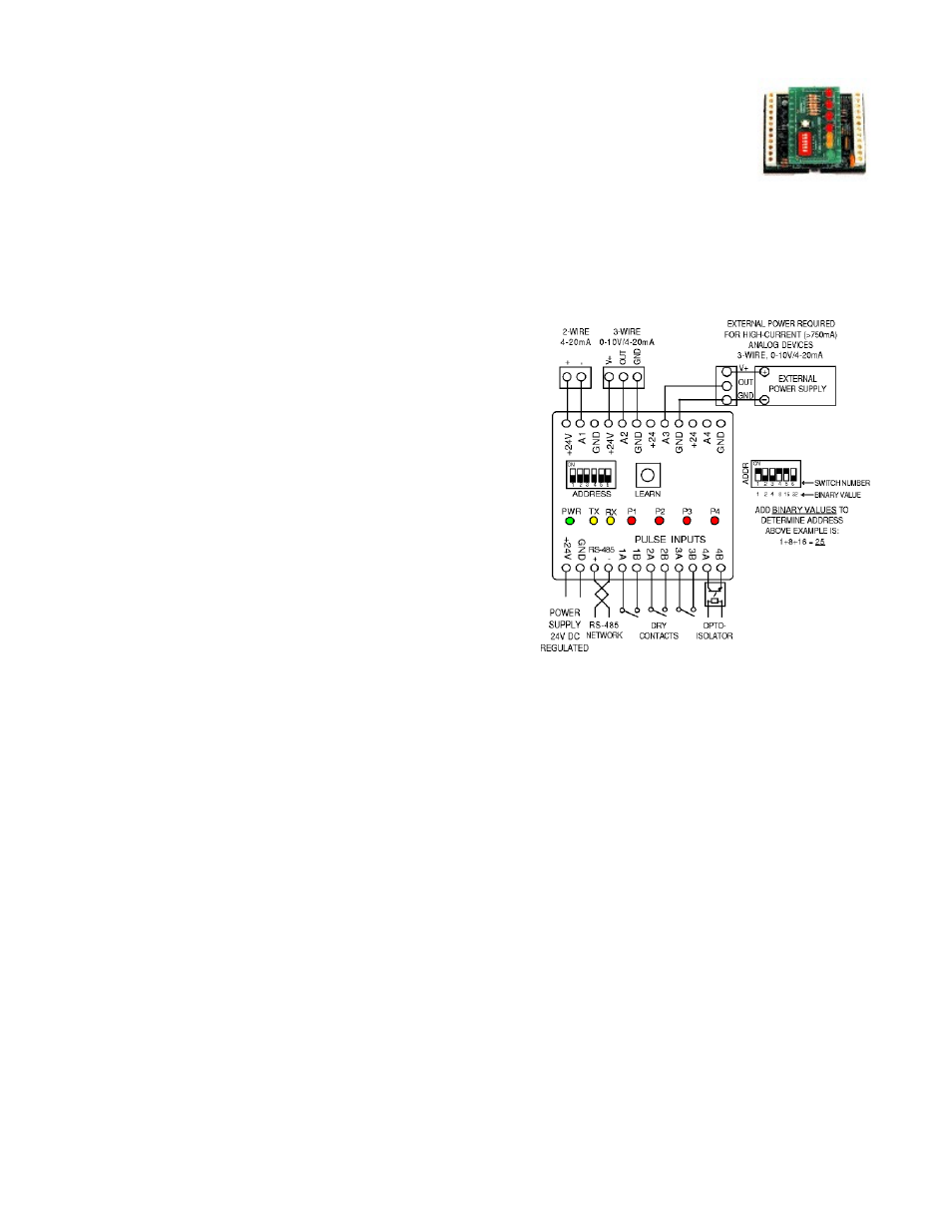
Installation, Wiring and Setup
1. Snap unit to existing DIN rail.
2. Connect power supply, network wiring, and sensor inputs as
indicated in wiring diagram.
3. Select network address as indicated by the diagram. Each
modbus device must have a unique address.
4. Auto-detect analog inputs: Make sure all analog devices are
properly installed and powered. Press the “LEARN” button.
Inputs will automatically be identified as 4-20mA or 0-10v.
5. Verify pulse inputs: Contact closure on pulse inputs will cause
red pulse LEDs to blink. Verify each pulse input is functioning
properly.
Modbus Point Map
Address Function
Range
Address
Function
Range
40001
Analog 1 Instantaneous reading.
0-4095
40017
Pulse State Register
*See Note.
40002
Analog 2 Instantaneous reading.
0-4095
40018
Pulse 1 ontime LSW (seconds)
40003
Analog 3 Instantaneous reading.
0-4095
40019
Pulse 1 ontime MSW (seconds)
40004
Analog 4 Instantaneous reading.
0-4095
40020
Pulse 2 ontime LSW (seconds)
40005
Pulse 1 LSW
40021
Pulse 2 ontime MSW (seconds)
40006
Pulse 1 MSW
40022
Pulse 3 ontime LSW (seconds)
40007
Pulse 2 LSW
40023
Pulse 3 ontime MSW (seconds)
40008
Pulse 2 MSW
40024
Pulse 4 ontime LSW (seconds)
40009
Pulse 3 LSW
40025
Pulse 4 ontime MSW (seconds)
40010
Pulse 3 MSW
40026
Analog 1 min
0-4095
40011
Pulse 4 LSW
40027
Analog 1 average
0-4095
40012
Pulse 4 MSW
40028
Analog 1 max
0-4095
40013
Status Register
*See Note.
40029
Analog 2 min
0-4095
40014
Firmware Version (111 = 1.11)
40030
Analog 2 average
0-4095
40015
Uptime Seconds LSW (seconds)
40031
Analog 2 max
0-4095
40016
Uptime Seconds MSW (seconds)
40032
Analog 3 min
0-4095
40033
Analog 3 average
0-4095
40034
Analog 3 max
0-4095
40035
Analog 4 min
0-4095
40036
Analog 4 average
0-4095
40037
Analog 4 max
0-4095