ONICON D-1200 Series User Manual
ONICON Measuring instruments
11451 Belcher Road South, Largo, FL 33773 • USA • Tel +1 (727) 447-6140 • Fax (727) 442-5699
www.onicon.com • [email protected]
D-1200 SERIES DISPLAY MODULE
INSTALLATION INSTRUCTIONS AND WIRING DIAGRAM
0610-1
05-14
SITE SELECTION
Find an easily accessible location where wire connections can be made and meter readings can be
taken from floor level. Mount the Display Module enclosure on a vibration free surface. Avoid
locations such as the plenum of a fan coil, heat exchanger, VFD or any housing that may contain
electric motors or other strong sources of electrical interference.
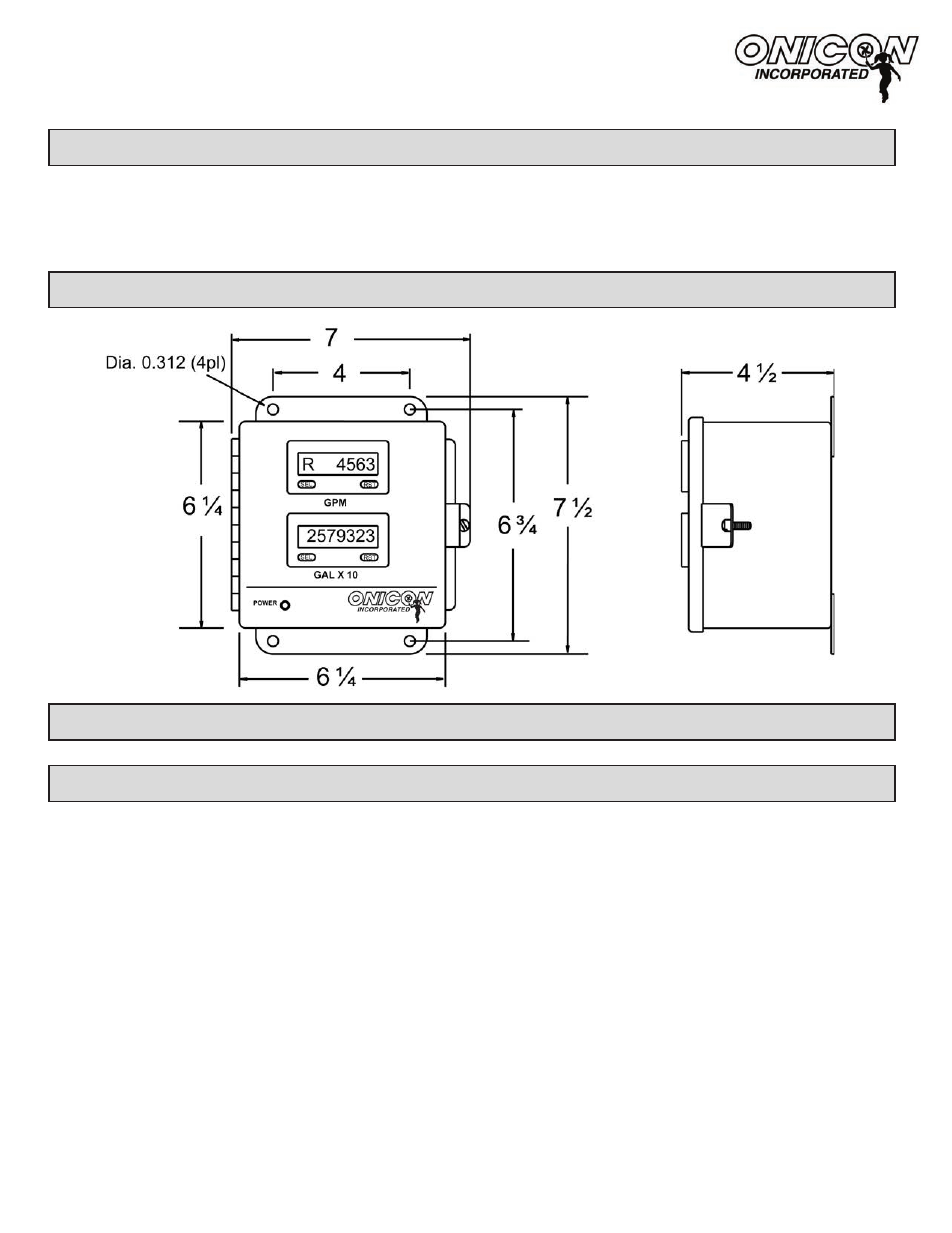
MECHANICAL INSTALLATION
ELECTRICAL INSTALLATION -
(Contact ONICON for a wiring diagram specific to the serial number of your display.
)
OPERATING THE DISPLAY MODULE
•
When power is applied to the display module, the power on LED will light and the black
LCD display segments will illuminate. The display(s) will indicate flow data if the flow
meter(s) is connected and there is flow in the pipe.
•
The letter “R” will precede the displayed value when the display is indicating a flow rate
such as GPM. Values shown without “R” preceding the number are totals.
•
For displays configured to indicate both rate and total, use the SEL button to toggle the
display between rate and total values.
• Engineering units and multipliers are shown immediately below the display as shown
above. Multiply the current reading by the mulitplier to determine the correct rate
and/or total.
• The RST button, if enabled, will reset accumulated totals to zero when pressed. ONICON
display modules are shipped with the RST button disabled. Contact ONICON if you wish
to enable this function. The display will indicate “Cnt OVEr” when the total exceeds the
maximum count.