OpenEye VS201 Quick Start User Manual
Ne-vs201 | 1 channel video encoder quick guide
This quick operation guide is a quick reference for users to connect and install the video
server and only provides basic information on the device’s settings and operation. For details,
refer to the User Manual.
Connections
NE-VS201 | 1 Channel Video Encoder Quick Guide
30057AA
Copyright ©2010 OpenEye. All Rights Reserved. Information contained in this document is subject to
change without prior notice. OpenEye does its best to provide accurate information but cannot be held
responsible for typos or mistakes.
A12931
23221 E Knox Ave
Liberty Lake, WA 99019
1.888.542.1103
Rear
Connecting to the Video Server
To access the setup menu, you need to install the viewer software on your PC or DVR. The
viewer software will install automatically the fi rst time you connect to the camera. If your inter-
net browser doesn’t install the viewer software, check the security settings or ActiveX controls
and plug-in settings. If your internet browser asks for permission to install the ActiveX control,
you must allow the ActiveX control to continue the installation.
To enable installation of ActiveX controls on Internet Explorer:
From the Tools menu, click Internet Options.
Click the Security tab and then click the Internet icon.
Click Custom Level and ensure that all ActiveX controls and plug-ins are set to
Enable or Prompt.
To add the camera to your trusted sites:
From the Tools menu, click Internet Options.
Click the Security tab and then click the Trusted Sites icon.
Click Sites.
Type the IP Address of the camera. Ensure that the Require server verifi cation check
box is cleared.
For additional information on adjusting the settings of your internet browser contact your sys-
tem administrator or refer to FAQ #1914 at openeye.net.
1.
2.
3.
1.
2.
3.
4.
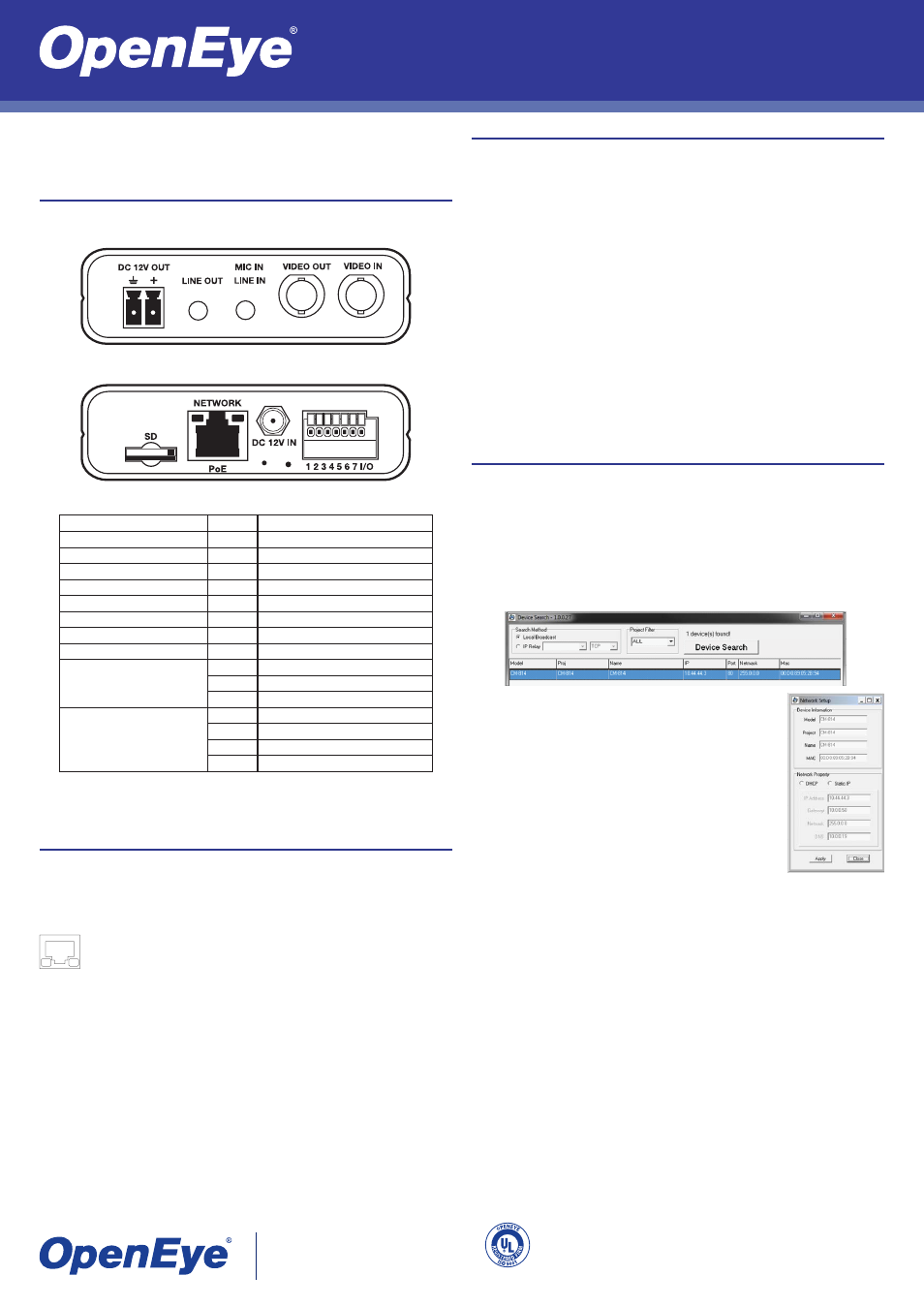
Assigning an IP Address
OpenEye IP devices come with the default IP address 192.168.0.250. To reset the IP address,
use the OpenEye Camera Finder application to set a new static IP, or use DHCP.
The OpenEye Camera Finder application is included on the accompanying software CD or
can be downloaded at www.openeye.net.
Open the Camera Finder application.
Click Device Search.
On the list of connected IP devices locate the desired camera and record the
MAC address.
1.
2.
3.
Right-click the camera row and select Network Setup.
Select Static IP and type the new IP address and other network
information in the appropriate boxes.
- or -
Select the DHCP option on the Network Setup window and then
click Apply.
Click OK to acknowledge the change.
After one minute, click Device Search to search for all connected
IP devices.
Locate the camera using the MAC address recorded earlier and
double click the camera row.
Type the Username and Password to access the camera.
4.
5.
6.
7.
8.
9.
The username and password are case sensitive. It is strongly recommended that the pass-
word be changed after the initial setup to prevent unauthorized access.
Username – Admin
Password – 1234
Network Installation
Tip
Connect the video cable to the video server before connecting power. If you connect
the power fi rst the video server may not detect the video signal.
Front
Connector
Pin No.
Defi nition
DC 12V OUT
-
Power Connection
LINE OUT
-
Audio Output
MIC IN / LINE IN
-
Audio Input and Microphone Input
VIDEO OUT
-
Analog Video Output to Monitor
VIDEO IN
-
Analog Video Input to Video Server
SD
-
Micro SD Card Slot
NETWORK / PoE
-
RJ-45 10/100 Mbps Ethernet / PoE
DC 12V IN
-
Power Input
RS-485
1
D+
2
D-
3
GND
ALARM I/O
4
GND
5
IN+
6
OUT-
7
OUT+
Connect one end of a CAT5 Ethernet cable to the Ethernet port (RJ45) on the video server
and the other end to the network switch or the DVR.
Note
If you are connecting the video server directly to a DVR, a crossover cable may be
necessary.
Check the status of the network connection by looking at the link indicator and
activity indicator LEDs. If the LEDs are not lit check your network connection. The
green link LED indicates a network connection and the orange activity LED fl ashes
to indicate network activity.