OpenEye CM-814 Quick Start User Manual
Cm-814 | high speed dome ip camera quick guide
This quick operation guide is a quick reference for users to install and operate the dome
camera and only provides basic information on the camera’s settings and operation. Before
attempting to connect, confi gure and operate the dome camera, please read the installation
guide and the user manual thoroughly.
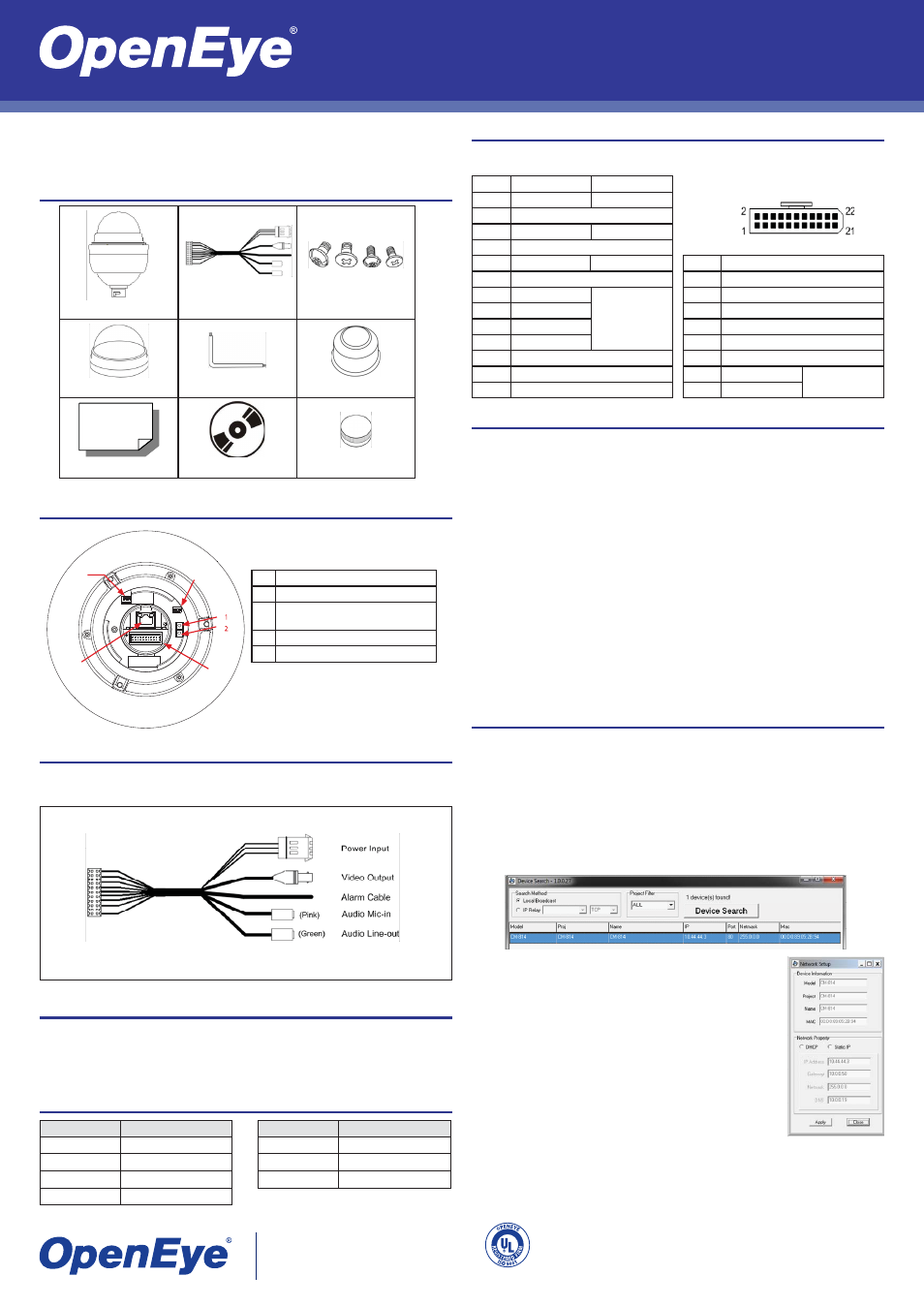
Dome Switch Defi nition
A
Communication Switch (reserved)
B
ISP Connector (for FW upgrade)
C1
C2
Reboot
Reset Factory Settings
D
22-Pin Connector
E
RJ45 Connector
All-in-one Data Cable
(24vAC)
CM-814 Camera
Screws
Optical Cover
Security Torx Tool
Waterproof Gasket
Quick Start Sheet
CD
Lubricant
Box Contents
Data Cable and Connector Defi nition
The data cable supplied with the dome camera is an 24vAC.
Refer to the fi gures below for the defi nition of each connector before wiring.
Grounding Recommendation
The GND (ground) wire must be directly connected to the middle pin of the 24vAC power con-
nector. Failure to connect the ground can cause damage and failure of the camera.
If the connection of the GND wire causes video noise, use a video isolator. This is only neces-
sary in some situations.
Power Wire Length Specifi cations
CM-814 | High Speed Dome IP Camera Quick Guide
24vAC Data/Alarm Cable
Note The CM-814 outdoor dome camera only supports 24vAC
Wire Gauge
Maximum Distance
22
27 feet
20
44 feet
18
69 feet
16
110 feet
A
B
C
D
E
C
22-Pin Connector Defi nition
When cabling, refer to the fi gure and table below for information about the defi nition of each
pin on the data cable.
22-Pin Connection
Pin
Defi nition
Cable
1
AC 24-1/DC (+)
20AWG/18AWG
2
ALM NC
3
AC 24-2/DC (-)
20AWG/18AWG
4
ALM NO
5
FG
20AWG/18AWG
6
ALM COM
7
Audio In
24AWG
8
Audio Out
9
Audio GND
10
Audio GND
11
ISOG
12
ALM-1
13
ALM-3
30053AA
Copyright ©2010 OpenEye. All Rights Reserved. Information contained in this document is subject to
change without prior notice. OpenEye does its best to provide accurate information but cannot be held
responsible for typos or mistakes.
A12931
23221 E Knox Ave
Liberty Lake, WA 99019
1.888.542.1103
Connecting to the IP Camera
To access the CM-814 setup menu, you need to install the viewer software on your PC or
DVR. The viewer software will install automatically the fi rst time you connect to the camera. If
your internet browser doesn’t install the viewer software, check the security settings or ActiveX
controls and plug-in settings. If your internet browser asks for permission to install the ActiveX
control, you must allow the ActiveX control to continue the installation.
To enable installation of ActiveX controls on Internet Explorer:
From the Tools menu, click Internet Options.
Click the Security tab and then click the Internet icon.
Click Custom Level and ensure that all ActiveX controls and plug-ins are set to En-
able or Prompt.
To add the camera to your trusted sites:
From the Tools menu, click Internet Options.
Click the Security tab and then click the Trusted Sites icon.
Click Sites.
Type the IP Address of the camera. Ensure that the Require server verifi cation check
box is cleared.
For additional information on adjusting the settings of your internet browser contact your sys-
tem administrator or refer to FAQ #1914 at openeye.net.
1.
2.
3.
1.
2.
3.
4.
Wire Gauge
Maximum Distance
14
175 feet
12
279 feet
10
444 feet
14
ALM-2
15
ALM-4
16
Reserved
17
Reserved
18
Reserved
19
Reserved
20
ALM GND
21
VGND
20AWG
22
Video
Assigning an IP Address
OpenEye IP cameras come with the default IP address 192.168.0.250. To reset the IP ad-
dress, use the OpenEye Camera Finder application to set a new static IP, or use DHCP.
The OpenEye Camera Finder application is included on the accompanying software CD or
can be downloaded at www.openeye.net.
Open the Camera Finder application.
Click Device Search.
On the list of connected IP devices locate the desired camera and record the
MAC address.
1.
2.
3.
Right-click the camera row and select Network Setup.
Select Static IP and type the new IP address and other network
information in the appropriate boxes.
- or -
Select the DHCP option on the Network Setup window and then
click Apply.
Click OK to acknowledge the change.
After one minute, click Device Search to search for all connected
IP devices.
Locate the camera using the MAC address recorded earlier and
double click the camera row.
Type the Username and Password to access the camera.
4.
5.
6.
7.
8.
9.
Default Username and Password
The username and password are case sensitive. It is strongly recommended that the pass-
word be changed after the initial setup to prevent unauthorized access.
Username – Admin
Password – 1234