Pennco NATURAL GAS TO LP User Manual
Conversion instructions, Natural gas to lp (sea level to 2000 feet), Warning
P/N 24004821, Rev. D [11/2014]
CONVERSION INSTRUCTIONS
NATURAL GAS TO LP (SEA LEVEL TO 2000 FEET)
Cast Iron Gas Fired Water Boilers
15B, BWB, UH15B, GMGWB
For Forced Hot Water
WARNING
This conversion kit shall be installed by a qualified
service agency in accordance with the manufacturer’s
instructions and all applicable codes and requirements
of the authority having jurisdiction. If the information
in these instructions is not followed exactly, a fire,
an explosion or production of carbon monoxide may
result causing property damage, personal injury or
loss of life. The qualified service agency is responsible
for the proper installation of this kit. The installation
is not proper and complete until the operation of the
converted appliance is checked as specified in the
manufacturer’s instructions supplied with the kit.
!
KIT CONTENTS
ITEM
QTY.
Installation Instructions
1
Conversion Plate/Label
1
Pilot Orifice - Spark
1
Pilot Orifice - 24 Volt
1
Liquid Sealing Compound
1
Spring Kit
1
Tools Required
Flat Head Screwdriver, 1/4” Nut Driver, 7/16” Open Ended
Wrench, 3/16” Allen Wrench, 18” Manometer (or dial
manometer)
Installation
1.
Turn off gas supply to the boiler.
WARNING
Electrical shock hazard. Turn OFF electrical power
supply at service panel before making electrical
connections. Failure to do so could result in death
or serious injury.
!
2.
Turn off all electrical to boiler.
3.
Remove front panel.
4.
Remove burner access door.
5.
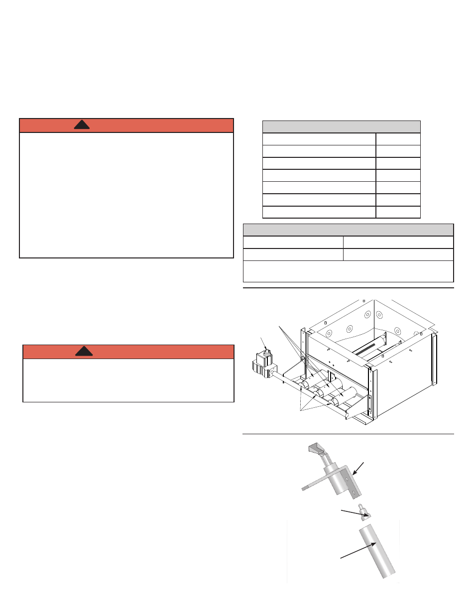
Remove main gas burner tubes. See Figure 1.
6.
Remove main burner orifices. See Figure 1.
7.
Install supplied LP gas main burner orifices. See Table3
for orifice size and quantities.
8.
Use 7/16” wrench, disconnect pilot tube from pilot. See
Figure 2.
9.
Remove pilot orifice. See Figure 2.
10.
Install LP gas pilot orifice. See Figure 2.
11.
Apply liquid sealing compound to threads of pilot
assembly fitting.
12.
Attach pilot tube to pilot and securely tighten. See
Figure 2.
13.
Replace main gas burner tubes.
14.
Remove the cover screw from gas valve pressure
regulator. See Figure 4.
PILOT ORIFICES
MFG.
PART NUMBER
Honeywell
390686-36*
*Use 390686-40 for Boilers Manufactured before July
2008 with Q381 Pilot.
GAS VALVE
KNOB
ORIFICES
BURNERS
Figure 1
Figure 2
Pilot Orifice
Pilot
Pilot Tube