Protech Audio 5053B User Manual
Protech, 5053b
Protech Audio Corporation 192 Cedar River Road, Indian Lake New York, 12842 Voice 518-648-6410 Fax 518-648-6395
PROTECH
MODELS COVERED
The Model 5053B Remote Microphone Station is designed
for use in engineered sound systems. The 5053B allows
the audio to be amplified at the source, and prevents the
serious degradation of signal-to-noise ratios normally
found when microphone level signals are caried over long
distances. Typical installations include airport terminals,
convention centers, and sports arenas.
The Model 5053B incorporates a number of features that
allow it to perform in a variety of venues. The unit has a
transformer balanced input, a transformer balanced out-
put, adjustable gain, phantom power capability, and a busy
buss indicator.
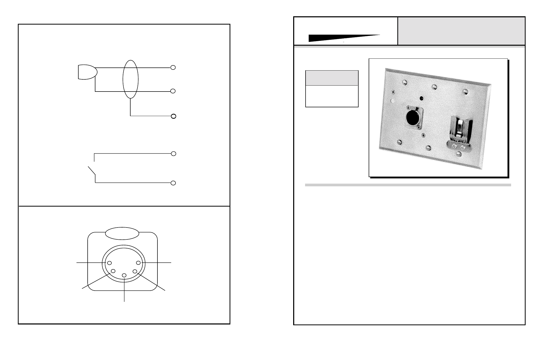
The input section starts with the panel mounted 5 pin
female XLR Connector. The connector allows wiring of
any low impedance microphone with a push-to-talk switch.
Pressing the push-to-talk switch activates an internal relay,
which connects the output transformer to the output
wiring. By disconnecting the output from the load, many
units can be wired to a single receiving device, without the
problem of loading the line. The XLR connector can be
configured to accept prewired microphones. The unit is
shipped from the factory wired with pin #1=shield, pin
#2= Audio Hi, pin #3= Audio Lo, and pins 4 & 5= audio
output switch closure.
The XLR audio input connects to the low impedance
microphone input transformer. The Model 5053B has
provision to allow strapping of the center-tap on the
transformer primary, to the 24VDC, to provide phantom
power to microphones requiring that feature.The gain of
the opamp section is adjustable with a small screwdriver,
thru the small hole located in the upper left hand of the
front panel. The unit has been shipped from the factory
with the gain adjusted to 45dB, into a 600 ohm load. The
minimum recommended gain setting is 35dB.
The output section consists of a high quality audio output
transformer, followed by a double-pole, double-throw
relay. Pressing the push-to-talk switch activates the relay,
and connects the output transformer to the audio output
wiring. The only other wiring required is for the 24VDC
power.
One additional conductor may be used to connect the
optional busy buss. When the push-to-talk switch is
activated, the front panel busy indicator will illuminate. By
wiring the buss pins together, all busy indicators wired
together will illuminate when any push to talk switch is
activated.
For additional information, contact:
APPLICATIONS ASSISTANCE
REMOTE MICROPHONE STATION
INSTALLATION & OPERATION MANUAL
®
5053B
XL CONNECTOR WIRING
5
4
3
2
1
5
4
1
3
2
www.
protechaudio
.com
1/06