Radionic G Series User Manual
G series, Led undercabinet light fixture, Prepare fixture
G Series
LED Undercabinet Light Fixture
For G8WH, G14WH, G22WH, G32WH, G40WH
Radionic Hi-Tech Inc.
1
For complete warranty terms see www.Radionic.net/Warranty
Safety Precautions
Read all safety precautions and installation instructions carefully before
installing or servicing this fixture. Failure to comply with these instructions
could result in potentially fatal electric shock and/or property damage.
It is recommended that a qualified electrician perform all wiring. This fixture
must be wired in accordance with all national and local electrical codes.
Do not handle any energized fixture or attempt to energize a fixture with wet
hands or while standing on a wet or damp surface or in water.
FOR Model No: G Series: Do not interconnect/link more than 200 watts or
10 units.
Caution:
- Injury to persons and damage to the fixture and/or mounting
surface or property may result if the fixture is pulled from the surface. To
reduce the likelihood of such injury or damage, mount only on a surface that
is mechanically sound.
Caution: Make sure power is off at fuse or circuit breaker box. Check
power wires for damage or scrapes.
Warning: Do not install over a heat source. Do not install directly over water.
Such as: fish tanks, sinks, laundry tubs etc.
This fixture is U.L. listed for use with BX or Conduit indoor DRY
applications only.
ASSEMBLY INSTRUCTIONS
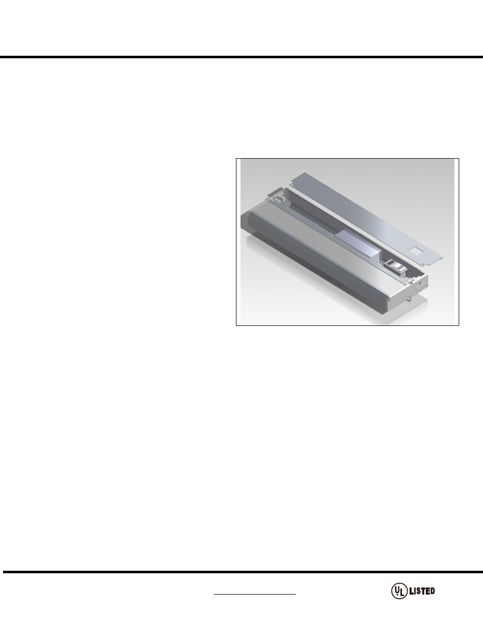
1. Prepare fixture
Disconnect electrical power and turn off circuit breaker before
installing or servicing any part of this fixture.
2. Mounting the fixture
A. Select a suitable sturdy dry mounting location (for indoor
applications only).
B. Secure the fixture using captive mounting screws (provided) or
toggle bolts (not provided) for hollow mounting applications.
Position the fixture in location for mounting. Drill holes in the
marked locations. Make sure that the fixture is very secure.
C. Only for G32WH & G40WH. Open top plate cover. Drill
additional mounting hole into the mounting surface and use extra
screw (not included).
D. To close cover – Carefully arrange wires so they do not get
pinched. Secure the top plate cover.
3. Plug –In Installation
This step should be skipped if using Hardwire Installation
A. Fixture must be mounted within 55” of an outlet, using only the
included 5’ power cord.
B. Refer to “2. Mounting the fixture” instructions for securely
mounting the fixture
C. Connect Cord to fixture by snapping the quick connect end of the cord to the corresponding connector in the end of the fixture marked “IN”. The cord will
only connect to the “IN” connector.
D. Install the 12” interconnecting cable (provided with the fixture) or direct/ butt connector (also provided with the fixture) if more than one fixture is to be used
(Note: Do not force the plug into the quick connect, the plugs are keyed to go in one way only).
E. Power can now be restored
4. Hardwire Installation
This step should be skipped if using 5’ Cord to Outlet
A. DO NOT USE INCLUDED 5’ POWER CORD if Hardwire Installation is used.
CAUTION: RISK OF SHOCK -
The plug blade will be
ENERGIZED
B. Open top plate cover using screw driver.
C. Refer to “2. Mounting the fixture” instructions for securely mounting the fixture.
D. Insert Cable Connector into the housing knockout. BX or Romex (not included)
E. Add 8” to the length of BX Cable for stripping purposes. Push the exposed wires (hot, neutral and ground) through and slide this bushing all the way down
to the exposed wires until it is snug up against the armor (for BX).
F . Using poke-in wire connectors (provided), connect white supply wire to white lead from connector. Connect black hot supply wire to black lead from
connector and green ground wire to green ground wire (provided).
G. Do not mix wires. Pull on each wire lead to make sure connections are secure. Make certain no bare wires are exposed outside of wire connectors.
H.
Ensure that the polarity of the wire is correct.
I. Pull on each wire lead to ensure connections are secure. Make certain no bare wires are exposed outside of the wire connectors.
J . Arrange the wires neatly inside the housing. Reattach the aluminum top plate cover using screws provided.
K. To close cover – Carefully arrange wires so they do not get pinched. Secure the top plate cover.
5. Link or Direct/Butt Connect fixtures
A. First fixture in series can be Hardwired or Plugged-In.
B. Second fixture must be located with 11” of first fixture for use with linking cord on direct/butt connect directly end to end.
C. Make sure power is disconnected on all fixtures. The fixture switch should not be engaged.
D. Refer to “2. Mounting the fixture” instructions for securely mounting the fixture.
E. Connect the Linking cord to the “OUT” connector of the first fixture and into the “IN” connector of the second fixture. The connectors will fit only one way.
Do not force the connections.