RLE X-Connector User Manual
X-connector quick start guide
© Raymond & Lae Engineering, Inc. 2011. All rights reserved. RLE® is a registered trademark and Seahawk™, Falcon™, and Raptor™ are
trademarks of Raymond & Lae Engineering, Inc. The products sold by Raymond & Lae Engineering, Inc. are subject to the limited warranty, limited
liability, and other terms and conditions of sale set forth at http://rletech.com/RLE-Terms-and-Conditions.html.
Supplies for Installation
Included with the X-Connector
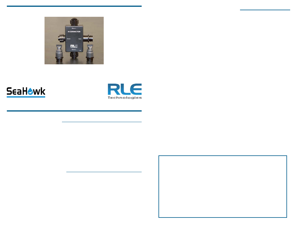
X-Connector device
Two end-of-line terminators (EOL)
Available from RLE, sold separately
SeaHawk Sensing cable
SeaHawk Non-sensing cable
SeaHawk SD-Z Spot Detector
SeaHawk Leak Detection Controller
X-Connector Functionality
The X-Connector uses internal, fi xed resistors to simulate 50 feet (15.24m) of
sensing cable per branch for Branch 1, Branch 2, and the Output. This creates a
buffer between the branches of the X-Connector, and eliminates confusion when
leaks occur at the beginning and end of the branches.
Even if you connect an EOL to the branch, the system will still interpret that
branch as using 50 feet (15.24m) of cable. Overall, the X-Connector simulates
150 feet (45.72m) of sensing cable.
X-Connector Quick Start Guide
Thank you for purchasing a SeaHawk X-Connector. This guide describes how to install the
X-Connector in a SeaHawk leak detection system.
If you need further assistance, please contact RLE Technologies via our website - http://
www.rletech.com/support or call us at 970.484.6510, Option 2.
Cable and Spot Detector Connections
Each branch of the X-Connector can accommodate sensing cable, non-sensing
cable, or an SD-Z spot detector. EOL terminators can be connected to Branch 1,
Branch 2, or the Output branch. Follow these steps to connect the appropriate
device to the X-Connector:
1. Connect the cable running from the controller - whether it’s the leader cable
that comes with most SeaHawk controllers, sensing cable, or non-sensing
cable - to the connector marked Input.
2. Connect
your
fi rst device - sensing cable, non-sensing cable, an SD-Z spot
detector, or an EOL - to Branch 1. Please remember, 50 feet (15.24m) of
cable is simulated between the Input branch and Branch 1. If you’re using
the device in conjunction with a distance-read controller, you’ll need to
account for this simulated length. Add 50 feet (15.24m) to the cable length
reading at the beginning of Branch 1. The diagrams on the back of this
sheet may clarify this concept for you.
3. Connect your second device to Branch 2. On distance read systems, add
50 feet (15.24m) from the Branch 1 cable end distance to the beginning
distance of Branch 2.
4. Connect your third device to the Output connector. On distance read
systems, add 50 feet (15.24m) from the Branch 2 cable end distance to the
beginning distance of the Output connector.
IMPORTANT - If you are not going to connect cable or a spot detector to a
particular branch connector or the output connector, you must attach an EOL
terminator to that branch. Without the EOL, your controller will report a cable
break. When you attach an EOL, you still must account for the 50 feet (15.24m)
of cable simulated by that branch.
Know your cable!
RLE’s orange sensing cable has a resistance of 2.8 ohms/foot. At this
resistance, the X-Connector’s internal resistors simulate 50 feet (15.24m)
of cable between branches.
Other sensing cable has a resistance of 4.0 ohms/foot. At this resistance,
the X-Connector’s internal resistors simulate 35 feet (10.67m) of cable
between branches.
Please verify your cable’s resistance before you program your leak
detection controller. If you have questions about the resistance of your
cable, refer to the cable’s data sheet.