Space Ray LTS Series Two Stage User Manual
Page 15
Form #43155040
-14-
May 2013
7.
Insert SJO cable through the strain relief bushing of the control box and connect to appropriate terminal
blocks. Refer to the wiring diagram in Section16.0) for the connection.
3/8 Connector
SJO Cable
(wire leads to appropriate terminal blocks,
refer to the wiring diagram in Section 16.0)
7
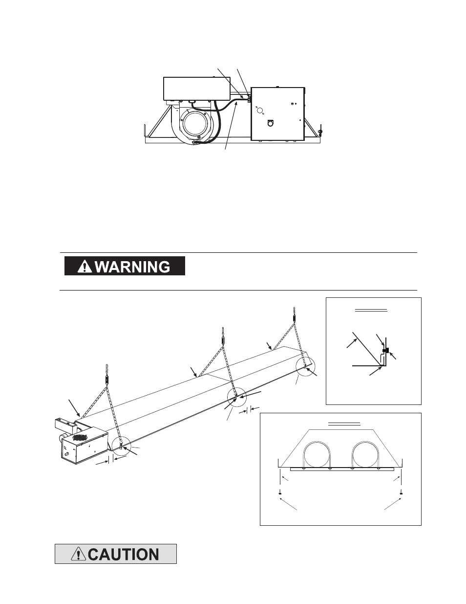
8.
Reflectors should overlap 1” to 3” and must be secured by sliding speed clips on the reflector edges. One
speed clip is required for each side of the reflector.
9.
Fasten the first reflector to the tube support/hanger bracket with (2) #10 sheet metal screws according
to Detail “A”. Mount the sliding reflector clamps (#42769010) per Reflector Clamp Installation (Detail “B”)
on all tube support/hanger brackets. Make sure the reflector can slide under the clamp during heater
operation.
The reflector clamps MUST be installed per reflector
The reflector clamps MUST be installed per reflector
The reflector clamps MUST be installed per reflector
The reflector clamps MUST be installed per reflector
clamp installation
clamp installation
clamp installation
clamp installation detail which allows the reflector to
detail which allows the reflector to
detail which allows the reflector to
detail which allows the reflector to
slide under the clamp during heater operation.
slide under the clamp during heater operation.
slide under the clamp during heater operation.
slide under the clamp during heater operation.
9
9
8
9
9
9
9
Tube Support &
Hanger Bracket
Reflector
Clamp
Reflector
Clamp
Screw
Reflector Clamp Installation
DETAIL B
DETAIL A
Fasten screws to tube
hanger/support bracket and reflector
(only the tube support/hanger
bracket closest to the control end)
#10 x 1/2 SHEET METAL
SCREWS (QTY - 2)
See Detail A & B
See Detail B
See Detail B
LTU(80-130) - 30 FT System Shown
2 overlap
3
(control box to reflector)
Do not relocate the tube support/hanger bracket at the control box end of
Do not relocate the tube support/hanger bracket at the control box end of
Do not relocate the tube support/hanger bracket at the control box end of
Do not relocate the tube support/hanger bracket at the control box end of
the heater. This will increase the weight on the emitter tube and can result
the heater. This will increase the weight on the emitter tube and can result
the heater. This will increase the weight on the emitter tube and can result
the heater. This will increase the weight on the emitter tube and can result
in prematur
in prematur
in prematur
in premature tube failure.
e tube failure.
e tube failure.
e tube failure.