5) lts series - adding optional 90º elbow, 6) lts series - adding optional corner reflector, 7) lts series - attaching control box assembly – Space Ray LTS Series Two Stage User Manual
Page 27
Form #43155040
-26-
May 2013
11.5)
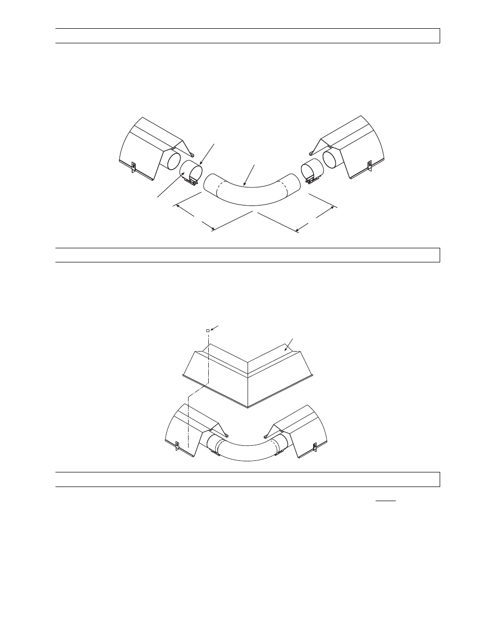
LTS SERIES - ADDING OPTIONAL 90º ELBOW
1.
The optional 90º elbow must be located a minimum of 10 ft. after the control box.
2.
Hang the body sections in a 90º ("L") shaped pattern. Allow spacing for the elbow. The distance from one
end of the elbow to the centerline of the opposite leg is 13" as shown.
3.
Join the tube ends of the body sections and the elbow together and secure with tube couplings as
described in Section 11.4).
90 Deg. Elbow
Tube
Coupling
13 (330mm)
13 (330mm)
Self-Drilling Screws
(QTY-2 per coupling)
11.6)
LTS SERIES - ADDING OPTIONAL CORNER REFLECTOR
1.
Place the corner reflector over the reflectors of both body sections.
2.
Secure by sliding speed clips on the reflector edges. One speed clip is required for each side of reflector.
3.
The corner reflector can be used only when the long axis of the heater is level and mounted in a
horizontal position.
11.7)
LTS SERIES - ATTACHING CONTROL BOX ASSEMBLY
1.
Attach the control box and gasket to end of tube flange and secure with 1/4-20 locknuts. NOTE:
NOTE:
NOTE:
NOTE: The
The
The
The control
control
control
control
box must be mounted to an
box must be mounted to an
box must be mounted to an
box must be mounted to an aluminized steel
aluminized steel
aluminized steel
aluminized steel bo
bo
bo
body section (12
dy section (12
dy section (12
dy section (12----radial
radial
radial
radial hole flange)
hole flange)
hole flange)
hole flange) for 40
for 40
for 40
for 40----200 MBtu/hr
200 MBtu/hr
200 MBtu/hr
200 MBtu/hr
models, or to a 10 ft. Alumi
models, or to a 10 ft. Alumi
models, or to a 10 ft. Alumi
models, or to a 10 ft. Alumi----Therm steel
Therm steel
Therm steel
Therm steel body section (6
body section (6
body section (6
body section (6----hole flange)
hole flange)
hole flange)
hole flange) for 225
for 225
for 225
for 225----250 MBtu/hr models,
250 MBtu/hr models,
250 MBtu/hr models,
250 MBtu/hr models,
regardless of configuration used.
regardless of configuration used.
regardless of configuration used.
regardless of configuration used. Fa
Fa
Fa
Failure to attach the control box to the flange end as indicated above will
ilure to attach the control box to the flange end as indicated above will
ilure to attach the control box to the flange end as indicated above will
ilure to attach the control box to the flange end as indicated above will
void the manufacturer’s warranty.
void the manufacturer’s warranty.
void the manufacturer’s warranty.
void the manufacturer’s warranty.
2.
A 3/8" connector is located on the left side of the control cabinet to provide strain relief for field wiring to
the draft inducer junction box (refer to Section 16.0) on Electrical Connections and Connection Wiring
Diagram for wiring between the control box and the draft inducer.)
3.
The control box must be mounted with the perforated fresh air plate on top, facing the ceiling.
Speed Clip
(QTY-4)
Corner
Reflector