0) instructions for pressure test gauge connection – Space Ray LTS Series Two Stage User Manual
Page 35
Form #43155040
-34-
May 2013
15.0)
INSTRUCTIONS FOR PRESSURE TEST GAUGE CONNECTION
SUPPLY PRESSURE
SUPPLY PRESSURE
SUPPLY PRESSURE
SUPPLY PRESSURE
1.
The installer will provide a 1/8” N.P.T. tapped plug, accessible for test gauge connection immediately
upstream of the gas supply connection to the heater.
MANIFOLD PRESSURE
MANIFOLD PRESSURE
MANIFOLD PRESSURE
MANIFOLD PRESSURE –
–
–
– COMBINATION GAS VALVE IS FACTORY SET
COMBINATION GAS VALVE IS FACTORY SET
COMBINATION GAS VALVE IS FACTORY SET
COMBINATION GAS VALVE IS FACTORY SET
1.
Turn the gas valve to the “OFF” position. Remove the 1/8” plug from the combination gas valve at the
Outlet Pressure T
Outlet Pressure T
Outlet Pressure T
Outlet Pressure Tap
ap
ap
ap shown below and connect a 1/8” nipple to the tapped hole. Connect the test gauge
to the nipple. Turn on the gas supply.
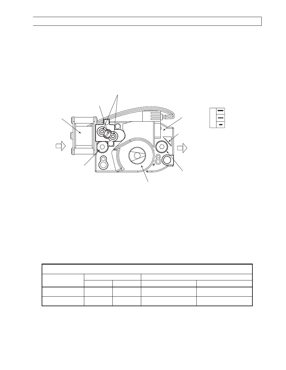
HI-LO
Adjustment Screws
(use 3/32 Hex
Allen Wrench)
1/8 NPT
Inlet Pressure
Tap with 3/16 Hex
Allen Wrench Plug
1/8NPT
Outlet Pressure
Tap with 3/16 Hex
Allen Wrench Plug
Gas Control
Knob
Wiring
Terminals (3)
Ground
Terminals (2)
OUTLET
INLET
CAUTION
Never jumper these terminals. This
shorts out valve coil and may burn
out heat anticipator in thermostat.
TWO-STAGE
GAS CONTROL VALVE
HI
LO
ON
OFF
LO
C
HI
Electric
Solenoid
Coil
Regulator
Vent Cover
2.
With the main burner operating, check the burner manifold pressure using a water column manometer.
Gauges that measure pressure in pounds per square inch are not accurate enough to measure or set the
manifold pressure. All measurements MUST BE
MUST BE
MUST BE
MUST BE made when this heater and all other gas burning
equipment that is connected to the gas supply system are operating at maximum capacity.
3.
The combination gas valve is factory set and should not require adjustment.
The combination gas valve is factory set and should not require adjustment.
The combination gas valve is factory set and should not require adjustment.
The combination gas valve is factory set and should not require adjustment. If full rate adjustment is
required, remove the cover screw. Using a small screwdriver, turn the adjustment screw clockwise
to
increase or counterclockwise
to decrease the gas pressure to the burner. Replace the cover screw.
NOTE: The step opening pressure of this gas valve is not adjustable.
NOTE: The step opening pressure of this gas valve is not adjustable.
NOTE: The step opening pressure of this gas valve is not adjustable.
NOTE: The step opening pressure of this gas valve is not adjustable.
4.
Check the burner at step pressure, observing burner ignition and flame characteristics. The burner should
ignite properly and without flashback to the orifice, and should remain lit.
GAS PRESSURE TABLE
GAS PRESSURE TABLE
GAS PRESSURE TABLE
GAS PRESSURE TABLE
GAS TYPE
GAS TYPE
GAS TYPE
GAS TYPE
MANIFOLD PRESSURE
MANIFOLD PRESSURE
MANIFOLD PRESSURE
MANIFOLD PRESSURE
SUPPLY PRESSURE
SUPPLY PRESSURE
SUPPLY PRESSURE
SUPPLY PRESSURE
High
High
High
High
Low
Low
Low
Low
Minimum*
Minimum*
Minimum*
Minimum*
Maximum
Maximum
Maximum
Maximum
Natural Gas
3.5” W.C.
1.4” W.C.
5” W.C.
1
14” W.C.
Propane Gas
10.0” W.C.
4.0” W.C.
11” W.C.
2
14” W.C.
* Minimum permissible gas supply pressure for purpose of input adjustment.
1
7” W.C. for LTS/U 150-200
2
12” W.C. for LTS/U 180-250