Space Ray LTS Series Two Stage User Manual
Page 41
Form #43155040
-40-
May 2013
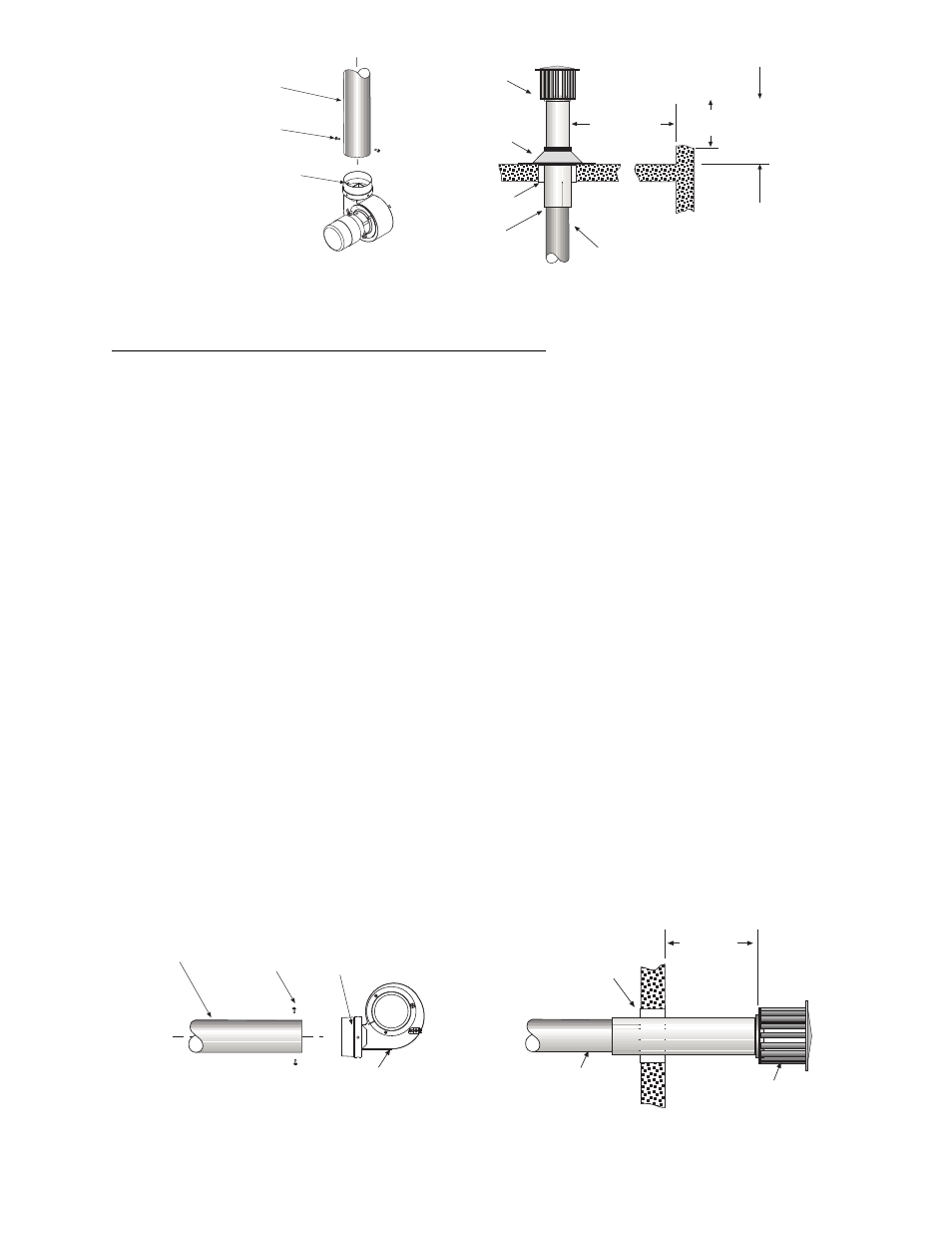
Vent Cap
Flashing
2 (5cm)
Clearance
Thimble
Seal Joint
and Annular
Space
10 ft (305cm)
or less
2 ft (77cm)
minimum
2 ft (77cm) minimum (when
no wall or parapet exists)
4 Diameter *
Vent
W
all or
Parapet
#10 Self-Drill
Screws
(typical)
4 Vent Pipe *
(vertical position)
Draft Inducer
(vertical position)
* 6 for LTS/U 180-250 Models
** 4x6 Adaptor included for LTS/U 180-250 Models
Starting Collar **
Note: Junction Box is not shown.
SINGLE HEATER VENTING (HORIZONTAL THROUGH SIDEWALL)
SINGLE HEATER VENTING (HORIZONTAL THROUGH SIDEWALL)
SINGLE HEATER VENTING (HORIZONTAL THROUGH SIDEWALL)
SINGLE HEATER VENTING (HORIZONTAL THROUGH SIDEWALL)
When venting the heater horizontally through a combustible outside sidewall, the same requirements listed
previously for venting Vertical Through The Roof
Vertical Through The Roof
Vertical Through The Roof
Vertical Through The Roof apply except as follows:
1.
A vent passing through a combustible wall must pass through an approved clearance thimble (Air-Jet
#4VT or Ameri-Vent #4EWT or other thimbles) that are listed by a nationally recognized testing agency.
Double-wall Type B vent must be used for the portion of the vent system which passes through the
combustible sidewall.
2.
An approved vent cap (Breidert or equal) must be attached to the end of the vent pipe.
•
4” vent – 25 ft. maximum with one 90° elbow and vent cap for 40-175 Models
•
6” vent – 75 ft. maximum with maximum two 90° elbows and vent cap for all Models
If other horizontal vent configurations are required, consult the manufacturer.
NOTE:
NOTE:
NOTE:
NOTE: To minimize problems associated with condensation in long horizontal runs, vent pipe can be insulated.
3.
When venting through a sidewall, the horizontal vent pipe shall rise not less than 1/4 inch per foot from
the start of the vent system to the vent terminal. All portions of the vent pipe shall be supported to
prevent sagging. (6’ spacing is recommended)
4.
A minimum clearance of 6 inches must be maintained between the outside wall and vent cap (18”
clearance will provide stability under high wind conditions).
5.
The horizontal venting system shall not terminate:
•
Less than 4 ft. (1.2m) below, 4 ft. (1.2m) horizontally from or 1 ft. (30cm) above any door, operable
window or gravity air inlet into any building. The bottom of the vent terminal shall be located at least 7 ft.
(2.1m) above grade or above snow accumulation level as determined by local codes.
•
Less than 3 ft. (0.9m) from a combustion air inlet.
•
Less than 3 ft. (0.9m) from any other building opening or any gas service regulator.
•
Less than 7 ft. (2.1m) above public walkways.
•
Directly over areas where condensate or vapor could create a nuisance or hazard or be harmful to the
operation of gas utility meters, regulators, relief valves, or other equipment. Building materials should
be protected from flue gases and condensate.
•
Less than 12” (0.30m) when directly below a combustible overhang.
6.
In regions of the country where prevailing winds are consistently higher than 40 mph, it may be
necessary to terminate the vent system above the roof level.
#10 Self-Drill
Screws
(typical)
4 Vent Pipe*
(horizontal position)
Sidewall Vent Cap
(Part No. 30297040: 4
Part No. 30297060: 6)
2 (5cm)
Clearance
Thimble
No less than 1/4 (6mm)
rise per foot (0.3m) toward
vent terminal
6 (15cm)
minimum
Draft Inducer
(horizontal position)
* 6 for LTS/U 180-250 Models
** 4x6 Adaptor included for LTS/U 180-250 Models
Note: Junction Box is not shown.
Starting Collar **