Space Ray LTS Series Two Stage User Manual
Page 42
Form #43155040
May 2013
-41-
MULTIPLE HEATER VENTING (CONNECTIONS INTO A COMMON VENT OR MANIFOLD)
MULTIPLE HEATER VENTING (CONNECTIONS INTO A COMMON VENT OR MANIFOLD)
MULTIPLE HEATER VENTING (CONNECTIONS INTO A COMMON VENT OR MANIFOLD)
MULTIPLE HEATER VENTING (CONNECTIONS INTO A COMMON VENT OR MANIFOLD)
Requirements for venting of multiple heaters are the same as described for SINGLE HEATER VENTING
SINGLE HEATER VENTING
SINGLE HEATER VENTING
SINGLE HEATER VENTING except as
follows:
1.
The common vent size and total vent height is normally determined by the number of heaters per
common vent, length of horizontal connector runs, and connector rise. Connector lengths should be as
short as possible and have a minimum 1/4 inch per foot rise. Without regard to connector rise and total
vent height due to many possible venting configurations, the following should be observed:
•
Common vent pipe & vent connector diameter should be no less than that shown in the following Vent
Sizing Table.
•
The connector length should be no more than 75% of the vertical portion of vent above the connector.
•
Where possible, use a Y-connector to the common vent.
2.
Material for connectors should be constructed of galvanized sheet metal or other approved
noncombustible corrosion resistant material as allowed by state or local codes. All common vent pipe
should be insulated flue pipe or double-wall, Type B vent.
3.
Avoid unnecessary bends. Limit to two (2) 90º elbows.
4.
The entire length of vent connector shall be readily accessible for inspection, cleaning and replacement.
5.
Groups of heaters with a common vent must be controlled by a common thermostat.
If any heater connected to a common vent system for multiple
If any heater connected to a common vent system for multiple
If any heater connected to a common vent system for multiple
If any heater connected to a common vent system for multiple
heaters is found inoperative, the heater should be disconnected from
heaters is found inoperative, the heater should be disconnected from
heaters is found inoperative, the heater should be disconnected from
heaters is found inoperative, the heater should be disconnected from
the vent system and its entrance into
the vent system and its entrance into
the vent system and its entrance into
the vent system and its entrance into the vent system capped.
the vent system capped.
the vent system capped.
the vent system capped.
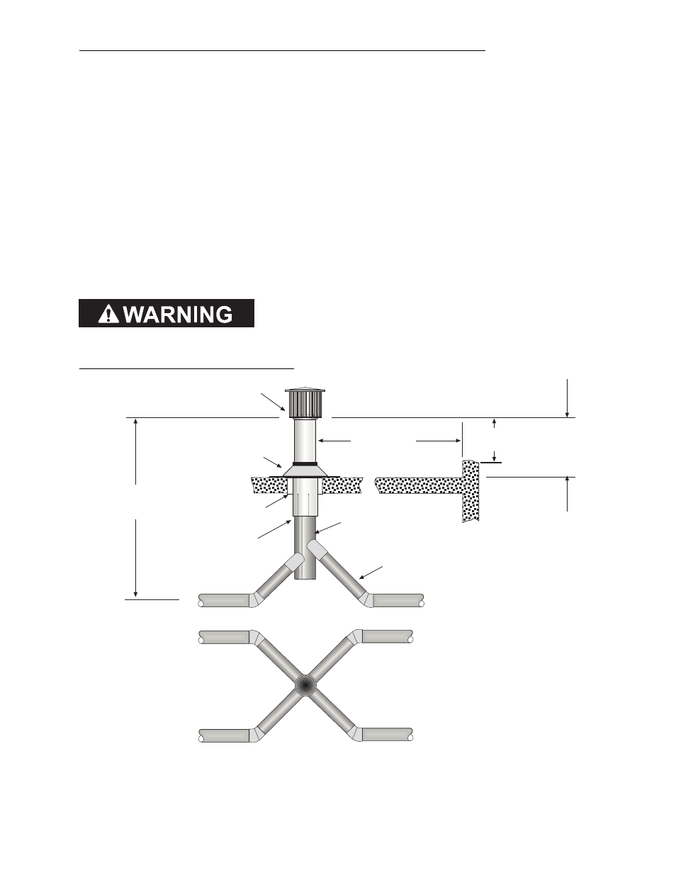
Multiple Heater Vertical Venting Arrangement
Total
vent
height
Vent Cap
Flashing
2 (5cm)
Clearance
Thimble
Seal joint
and annular
space
10 ft (305cm)
or less
2 ft (77cm)
minimum
2 ft (77cm) minimum
(when no wall or
parapet exists)
4 diameter
single wall vent
W
all or
Parapet
See Vent
Sizing Table for
diameter
Connections to the common vent
must be arranged to avoid direct
opposition of exhaust products.
Plan View