Draft inducer components – Space Ray LTS Series Two Stage User Manual
Page 58
Form #43155040
May 2013
-57-
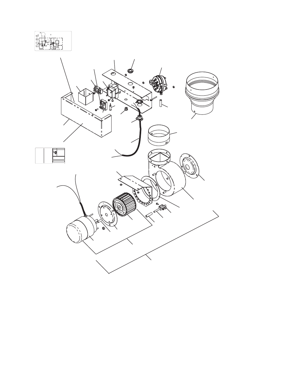
13
21
11,11a
4
10
19
18
16
14
15
17
22
39
40
Items 39 & 40 not included
in Draft Inducer Assembly
29-38c
Items not included
in Draft Inducer Assembly
5
27
7
8
4
3,3a
6
25
24
23
DRAFT INDUCER
COMPONENTS
1,2
9
1a,2a
16a
(not shown)
41
42
42874000 Rev. G 10/04
G
BL
BL
BK
BK
R
W
BK
BK
R
BK
W
BK
BK
W
DRAFT
INDUCER
MOTOR
GAS VALVE
AIR SWITCH
TRANSFORMER
120V PRIMARY
24V SECONDARY
A
G
R
IGNITION MODULE
HIGH VOLTAGE
CABLE
ELECTRODE
GAP 3/16
CONTINUE TO
ADDITIONAL
HEATERS
NEUTRAL
120V
THERMOST
A
T
GROUND
L1
L2
TERMINAL
BLOCK
FACTORY WIRING
FIELD WIRING
CONNECTION WIRING DIAGRAM
CONTROL CABINET
If any of the original wire as supplied with the
appliance must be replaced. It must be
replaced with wiring material having a
temperature rating of at least 105oC. (18
AWG. - UL / CSA 600V Type TEW)
When connecting the supply circuit to the
heater, wiring material having a minimum size
of 14 AWG and a temperature rating of at
least 90oC shall be used.
WIRE LEGEND
ENGLISH
FRANCAIS
BK
BLACK
NOIR
W
WHITE
BLANC
R
RED
ROUGE
BL
BLUE
BLEU
G
GREEN
VERT
A
AMBER
AMBRE
MONITORING LIGHTS
GND
(BURNER)
25V
(GND)
25V
VALVE VALVE
FUSE 2A
JUNCTION BOX
SJO CABLE
(NOT
INCLUDED)
W
R
BK
Schéma de circuit de connexion
Circuit d'origine
Connexions client
Lampes témoins
Neutre
Terre
Vers les autres
radiateurs
Plaque à
bornes
Transformateur
bobine primaire 120ÊV
bobine secondaire 24ÊV
pressostat
Robinet à gaz
Écartement
d'électrode
4,7Êmm
Haute tension
Armoire de commande
Bloc d'allumage
Moteur
d'amorce
d'aspiration
S'il faut remplacer un fil de l'appareil d'origine,
utiliser exclusivement des fils à température
de service nominale d'au moins 105C (18
AWG. - UL / CSA 600ÊV
Type TEW).
Pour raccorder le circuit d'alimentation au
radiateur, utiliser des fils de calibre 14 AWG
ou plus à température de service nominale
d'au moins 90C.
Fusible
Bloc de jonction
Câble SJO
(non compris)
Note: When venting a single
heater horizontally through a
combustible outside wall the
vent must pass through a 2
clearance thimble (Air Jet No.
4VT or Ameri-vent No 4EWT
for the 40 75,000 BTU
heaters and Air-Jet No 6VT or
Ameri-Vent No. 6EWT for the
80 250,000 Btu heaters) or
other thimbles which are listed
by nationally recognized testing
agency.
Attach a vent cap (Breidert No.
4L or equivalent for the 40-
75,000 BTU heaters or Breidert
No. 6L or equivalent for 80
250,000 BTU heaters) to the
end of the pipe.
Minimum equivalent length of
vent pipe = 5ft (1.5m)
Maximum equivalent length of
vent pipe = 75ft (23m)
THIS UNIT EQUIPPED WITH A
2 AMP IN LINE-FUSE FOR
OVERCURRENT PROTECTION
OF CONTROL CIRCUIT
ELECTRIC SHOCK
HAZARD
Disconnect electrical supply
before servicing
Failure to follow these
instructions may result in
death, serious injury or
property damage.
WARNING
DRAFT INDUCER SERIAL NUMBER
42922020 Rev C 8/05
SIDEWALL VENTING ONLY
UN MUR LATÉRAL A É R AT I O N