Wavetronix SmartSensor Matrix (SS-225) - Quick-reference Guide (Installer) User Manual
Smartsensor matrix, Installer quick-reference guide, Select the sensor’s location
SmartSensor Matrix
INSTALLER QUICK-REFERENCE GUIDE
www.wavetronix.com
801.734.7200
2
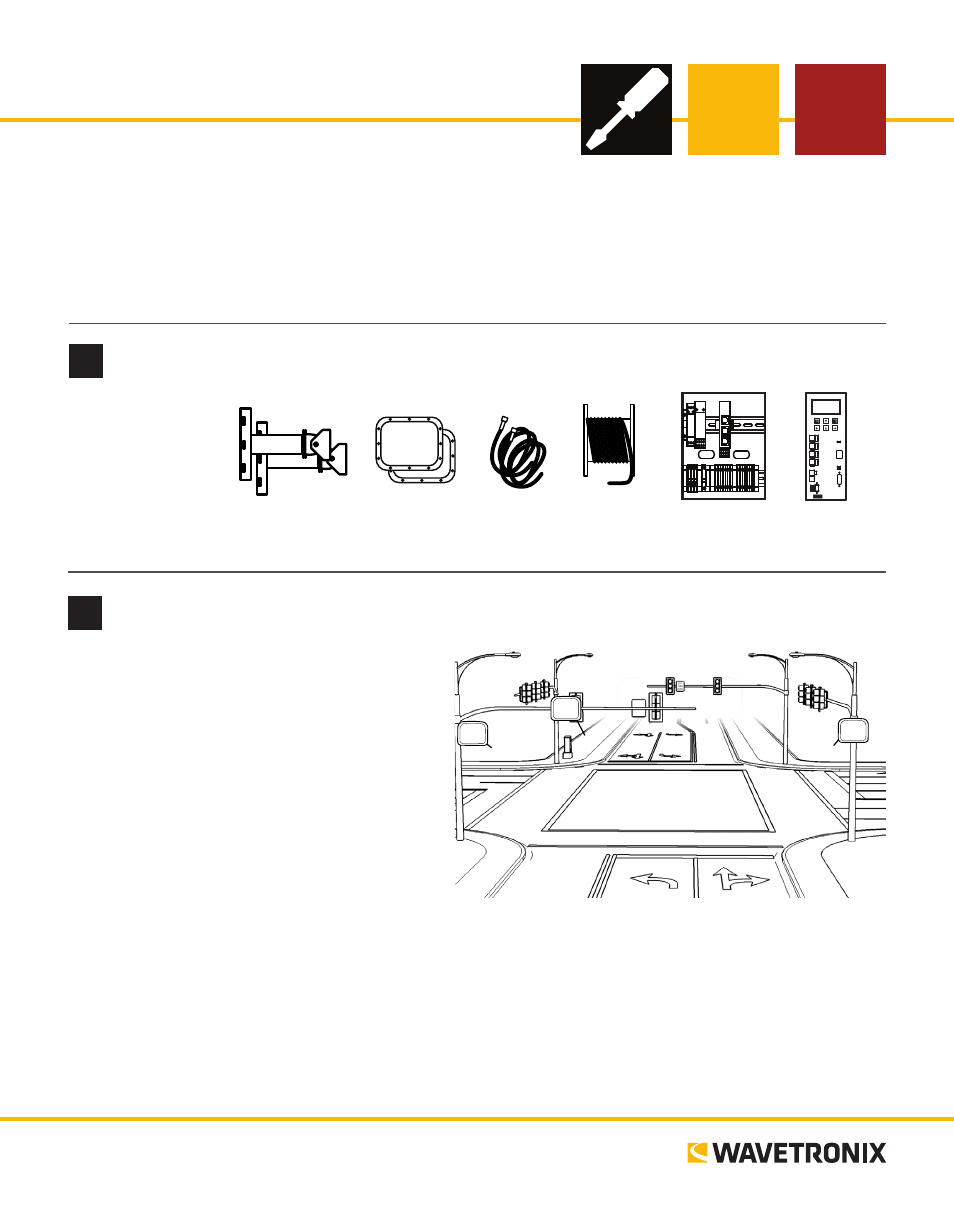
Select the sensor’s location
1
Ensure that all necessary components are available
Introduction
Complete the steps below to integrate the Wavetronix SmartSensor Matrix system into a signalized intersec-
tion. If you need technical support, please contact Wavetronix Technical Services at 801.764.0277. For more
information, see the SmartSensor Matrix User Guide.
The following are the suggested Matrix mount-
ing locations:
1 The back side of mast arm – Allows the
sensor to be placed near the lanes of interest
and may be the best location option for
wide approaches. Mount the sensor toward
the end of the arm, to avoid occlusion from
passing vehicles, but make there’s at least
6 ft. (1.8 m) lateral seperation between the
sensor and the first lane of interest.
2 The far side of approach – Usually mount-
ed on a corner vertical mast pole or strain
pole. If the sensor is mounted on a vertical pole with a mast arm, you can usually avoid occlusion by
mounting the sensor away from or below the mast arm.
3 The near side of approach – Typically best if detecting the left turn lane is less important; also allows
you to mount the sensor high enough to avoid occlusion.
Note. The sensor must be at least 6 ft. (1.8 m) from the first lane of interest—that is, if you drew a line from
the sensor to the ground, that line should hit the ground at least 6 ft. from the first lane you need to detect.
These components,
all available from
Wavetronix, may
be needed to install
your SmartSensor
Matrix.
Sensor
Mounts
Sensors
Accessory
Cables
SmartSensor
6-conductor
Cable
Preassembled
Backplate
➌
➋
➊
Mount
Brackets
Sensors
Accessory
Cables
Click 650
6-conductor
Cable
Preassembled
Backplate