Airaid 400-258 User Manual
Installation instructions, For part numbers, Component identification
Installation Instructions
For Part Numbers:
400-258
700-420 Airaid Oiled Media Filter
401-258
701-420 SynthaMax Dry Media Filter - Red
402-258
702-420 SynthaMax Dry Media Filter - Black
403-258
703-420 SynthaMax Dry Media Filter - Blue
1997-2004 Ford Expedition 4.6L, 5.4L V8
1997-2003 Ford F-150 4.6L, 5.4L V8
2004 Ford F-150 Heritage 4.6L, 5.4L V8
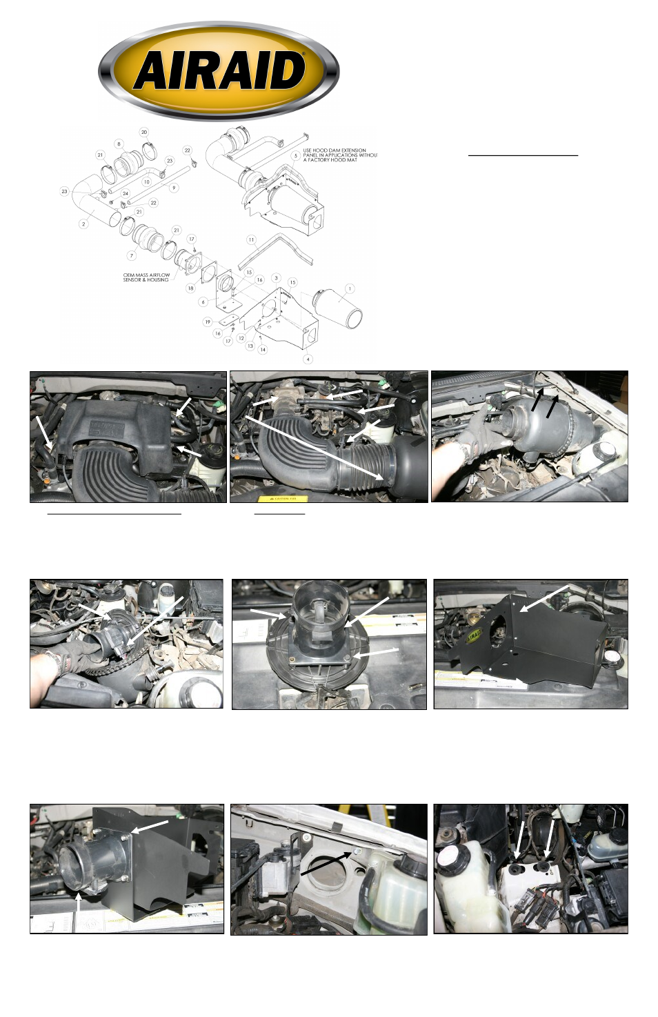
Component Identification
1.
Airaid Premium Filter
1
2.
Airaid Intake Tube
1
3.
MAF Panel
1
4.
Bottom Panel
1
5.
Panel Extension
1
6.
MAF Bracket
1
7.
Urethane Hump Hose
1
8.
Urethane Reducer Hump Hose
1
9.
5/8” x 18” Breather Hose
1
10.
3/4” x 12” L-Hose
1
11.
Weather Strip 23”
1
12.
6-32 x 5/16” Phillips Head Screw
9
13.
#6 Flat Washer
9
14.
6-32 Kep Nut
9
15.
1/4-20 x 7/8” Hex Head Bolt
6
16.
1/4” Flat Washer
4
17.
1/4” Nylock Nut
6
18.
MAF Gasket
1
19.
MAF Backing Plate
1
20.
#52 Hose Clamp
1
21.
#60 Hose Clamp
3
22.
#19 Speed Clamp
2
23.
#22 Speed Clamp
2
24.
Rubber Grommet
1
1. Disconnect the negative battery cable.
Using a 10mm socket, remove the three bolts that secure
the beauty cover over the throttlebody. Remove the cov-
er and save these parts for reinstallation in step #16.
2. A) Very carefully, using a pulling cir cular motion,
remove the air intake temperature sensor from the air
intake tube. B) Disconnect the upper, idle air bypass hose.
C) Disconnect the cr ankcase br eather at the intake
tube and the valve cover, and remove it from the vehicle.
D) Loosen two hose clamps and r emove the air intake
tube from the vehicle.
3. Lift straight up on the outlet side of the air filter canis-
ter to remove it from it’s locating grommets. Next, pull
it towards the engine to dislodge it from the inner fender
well.
4.Unlatch the clamp on the canister to separate the two
halves. Once separated, remove the factory air filter.
A) Next, slide the lar ge r ound plastic Mass Air Flow
(MAF) sensor adapter plate fr om the canister . To do
this, slide the wires thru the rubber grommet to gain
access to the MAF sensor wiring connector. Now dis-
connect the MAF sensor wiring harness, and remove the
MAF sensor housing and adapter plate. Remove the
remaining half of the canister from the vehicle.
5. Remove the bolts that secure the MAF sensor housing
to the adapter. Separate the adapter plate from the MAF
sensor housing and save the sensor and housing for rein-
stallation in step #7.
6. Assemble the MAF panel (#3), and bottom panel (#4)
as shown using four 6-32 screws (#12), four flat washers
(#13), and four Kep nuts (#14) as shown.
A.
B.
D.
7. Attach the MAF bracket (#6), rubber gasket (#18),
and factory MAF sensor housing to the Cold Air Dam
(CAD) using four 1/4-20x7/8” hex bolts (#15), and 1/4”
Nylock nuts (#17), as shown. Make sure that the MAF
sensor connector is on the bottom when assembly is
complete. Refer to the line drawing above for reference.
8. Using a 10mm socket, remove and save the bolt that
secures the radiator overflow tank to the driver side inner
fender well.
9. Remove the two grommets that held the air filter can-
ister in place. They will not be reused.
A.
MAF Connector
MAF Connector
Rubber Gasket
C.
MAF Housing