Airmar P79 User Manual
Installation instructions owner’s guide, In-hull, adjustable angle transducer
17
-2
17
-0
1 re
v.
1
1
12
/14
/10
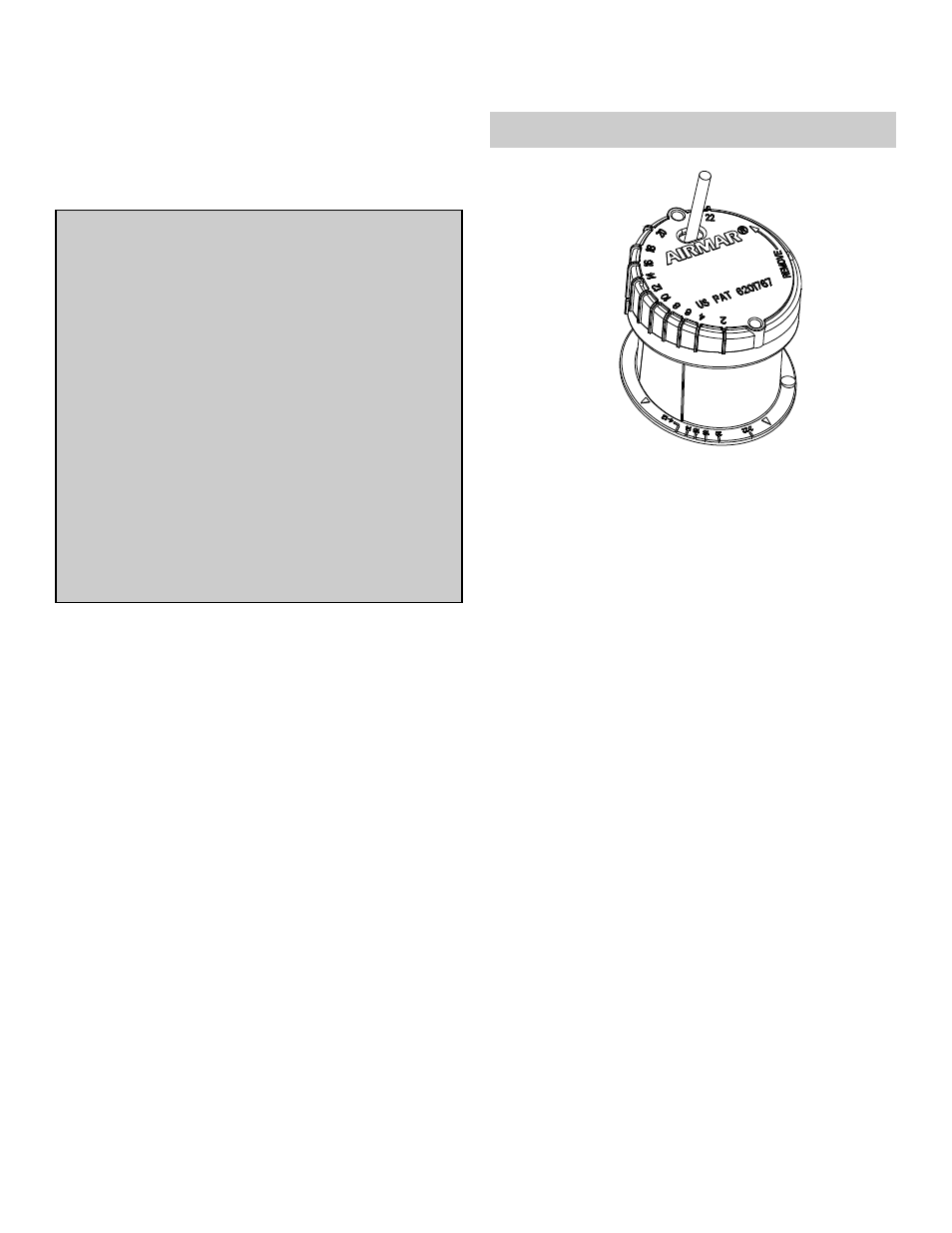
In-Hull, Adjustable Angle Transducer
Model P79
U.S. Patent No. 6,201,767. EP 1 118 074
Applications
• Fiberglass hulls only
• Recommended for high-speed powerboats and racing sailboats
• Accommodates a deadrise angle up to 22°
Tools & Materials
Safety goggles
Dust mask
Adhesive tape
Pole
Detergent (some installations)
Weak solvent (such as alcohol)
Disk sander (some installations)
Thin sealable plastic bag (some installations)
Cable ties (some installations)
Water-based lubricant (such as K-Y® jelly) (some installations)
Angle finder or digital level
Carpenter’s square
Pencil
Silicone sealant (such as GE Silicone I or Silicone II)
Screwdriver
Petroleum jelly (such as Vaseline® brand)
Propylene glycol (non-toxic antifreeze/coolant) 71ml (2.4 fl. oz.)
Level
Grommet(s) (some installations)
Installation in a cored fiberglass hull (see page 4):
Drill
Hole saw
100mm or 4"
Miniature disk sander
Casting epoxy (Polypoxy #7035/7040) or resin
Paper cup
Stirrer
Mounting Location
About Fiberglass Hulls
The fiberglass hull below the transducer must be solid. Since the
hull absorbs acoustic energy, transmitting through the hull
reduces the transducer’s performance. Fiberglass hulls are often
reinforced in places for added strength or to reduce weight. These
cored areas contain balsa wood or structural foam which are poor
sound conductors. Do not locate the transducer over coring.
Placement
CAUTION: Do not mount the transducer near water intake or
discharge openings or behind strakes, fittings, or hull irregularities
that will disturb the water flow.
Choose a location:
• Where the fiberglass is solid (no air bubbles are trapped in the
fiberglass resin) and where no coring, flotation material, or dead
air space is sandwiched between the inside skin and outer skin
of the hull.
• Where the hull below the transducer will be in contact with the
water at all times.
• Where the water flowing under the hull is smoothest with a
minimum of bubbles and turbulence (especially at high speeds).
• Away from interference caused by power and radiation sources
such as: the propeller(s) and shaft(s), other machinery, other
echosounders, and other cables. The lower the noise level, the
higher the echosounder gain setting that can be used.
• Where the transducer beam will not be blocked by the keel or
propeller shaft(s).
• Where the deadrise angle does not exceed 22°.
• Where there is space inside the vessel for the height of the unit,
tightening the locking ring, and installing the transducer.
Record the information found on the cable tag for future reference.
Part No._________________Date___________Frequency________kHz
INSTALLATION INSTRUCTIONS
OWNER’S GUIDE &
WARNING: Always wear safety goggles and a dust
mask to avoid personal injury.
CAUTION: The fiberglass hull below the transducer
must be solid. The transducer will not transmit through
coring material such as foam or balsa wood.
CAUTION: Do not use an epoxy adhesive because it
is too brittle.
CAUTION: Never pull, carry, or hold the transducer by
the cable. This may sever internal connections.
CAUTION: Never use solvents. Cleaners, fuel,
sealants, paint, and other products may contain strong
solvents, such as acetone, which attack many
plastics, greatly reducing their strength.
IMPORTANT: Please read the instructions completely
before proceeding with the installation. These
instructions supersede any other instructions in your
instrument manual if they differ.