Airmar 1 kW—M260 User Manual
Installation instructions owner’s guide, In-hull, 1kw transducer, Tools & materials
17
-4
46
-0
1 re
v.05
01
/12
/13
In-Hull, 1kW
Transducer
Models: M260, M265LH, M265LM
U.S. Patent No. 7,369,458. UK Patent No. 2 414 077. U.S. Patent Pending
Tools & Materials
Safety goggles
Dust mask
Rope
Detergent (some installations)
Weak solvent (such as alcohol)
Disk sander (some installations)
Thin sealable plastic bag (some installations)
Cable ties (some installations)
Water-based lubricant (such as K-Y
®
jelly) (some installations)
Carpenter’s level
Pencil
Saw
Scissors
Sand paper:
80 grit
Bonding material (see www.airmar.com for additional brands):
Fiberglass resin:
Bondo 401
West Marine #1937762)
or Marine-Tex epoxy putty (14 oz. pack)
or 3M™ Marine Adhesive/Sealant 5200
Propylene glycol (non-toxic anti-freeze/coolant)
Grommet(s) (some installations)
Torque wrench with Allen-wrench adaptor (recommended)
Applications
• Fiberglass hulls only
• Recommended for high-speed boats
• Accommodates a deadrise angle up to 30° with the longest side
of the tank installed parallel to the centerline (keel) of the hull.
Mounting Location
About Fiberglass Hulls
Since the hull absorbs acoustic energy, transmitting through the
hull reduces the transducer’s performance. Fiberglass hulls are
often cored in places for added strength or to reduce weight. These
cored areas contain balsa wood or structural foam which are poor
sound conductors. Do not locate the transducer over coring.
Choose a Location
• Where the fiberglass is solid (no air bubbles are trapped in the
fiberglass resin) and where no coring, flotation material, or dead
air space is sandwiched between the inside skin and outer skin
of the hull.
• Where the hull below the transducer will be in contact with the
water at all times.
• Where the water flowing under the hull is smoothest with a
minimum of bubbles and turbulence (especially at high speeds).
Do not mount the transducer near water intake or discharge
openings; or behind strakes, fittings, or hull irregularities.
• Where the transducer beam will not be blocked by the keel or
propeller shaft(s).
• Away from interference caused by power and radiation sources
such as: the propeller(s) and shaft(s), other machinery, other
echosounders, and other cables. The lower the noise level, the
higher the echosounder gain setting that can be used.
• Where the deadrise angle of the hull does not exceed 30°.
• Where there is space inside the vessel for the size of the tank
and removing the transducer.
• CHIRP transducer—Mount in a cool well-ventilated area away
from the engine to avoid overheating the liquid inside the tank.
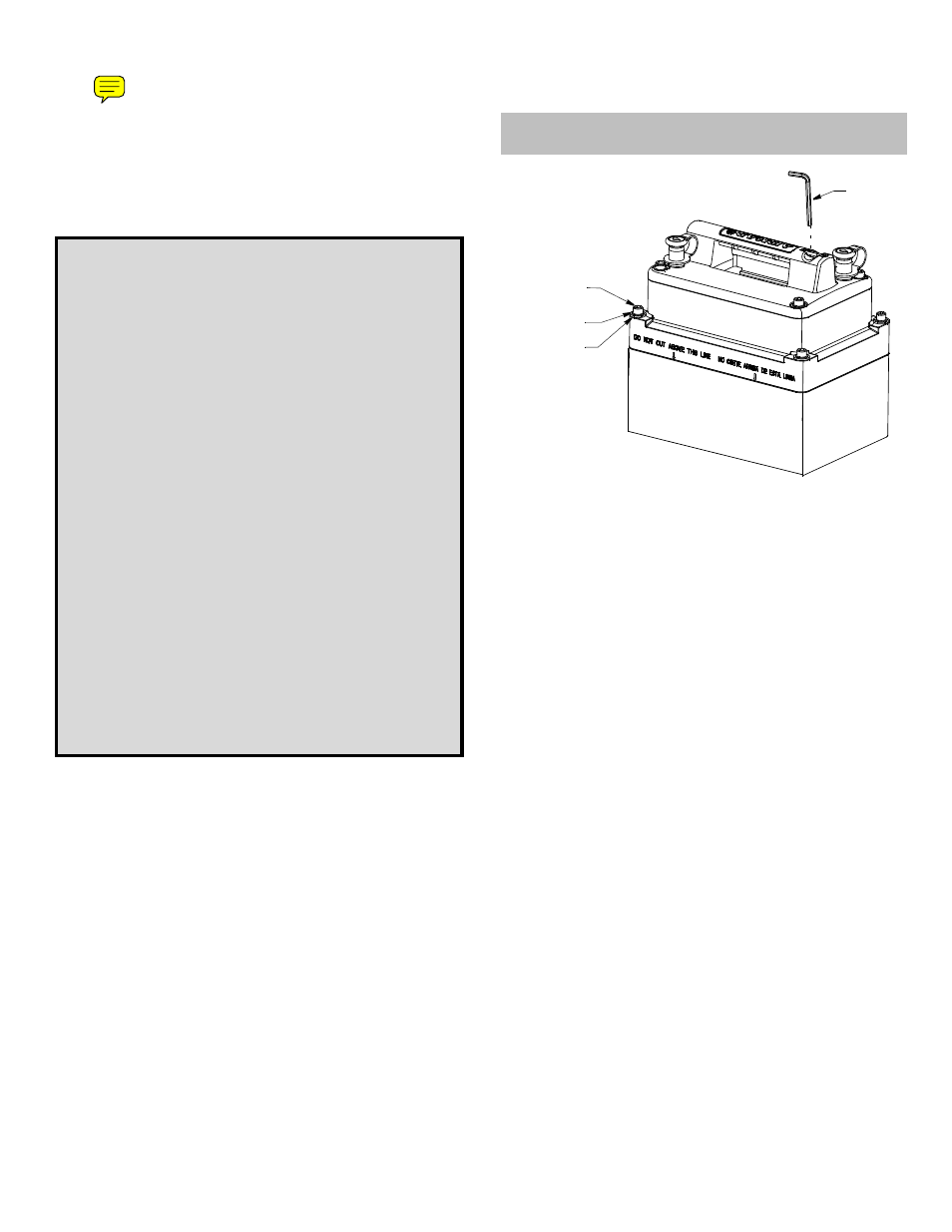
Figure 1. M260
lower section of tank
INSTALLATION INSTRUCTIONS
OWNER’S GUIDE &
Record the information found on the cable tag for future reference.
Part No._________________Date___________Frequency________kHz
Follow the precautions below for optimal
product performance and to reduce the risk of
property damage, personal injury, and/or death.
WARNING: Always wear safety goggles and a dust
mask when installing.
CAUTION: The fiberglass hull below the transducer
must be solid. The transducer will not transmit through
coring material such as foam or balsa wood.
CAUTION: CHIRP transducer—Do not install in the
engine compartment or other hot place. The
transducer may fail if the temperature of the liquid in
the tank exceeds 60° C (140° F).
CAUTION: CHIRP transducer—Always operate the
transducer in liquid. Operating in air will allow the
transducer to overheat resulting in failure.
CAUTION: Never pull, carry, or hold the transducer by
the cable. This may sever internal connections.
CAUTION: Never use solvents. Cleaners, fuel, sealant,
paint and other products may contain solvents that can
damage plastic parts, especially the transducer’s face.
IMPORTANT: Please read the instructions completely
before proceeding with the installation. These
instructions supersede any other instructions in your
instrument manual if they differ.
upper section of tank
socket head
flat washer (4)
lock washer (4)
cap screw (4)
Allen
wrench