Airmar Shorty™ with Valve—S300 User Manual
Installation instructions owner’s guide, Thru-hull, shorty, With valve speed & temperature sensor
17-
274-
01 rev. 04
04/
14/
11
Thru-Hull, Shorty
™
with Valve
Speed & Temperature Sensor
Models: S300, ST300
Applications
• Recommended for fiberglass or metal hull only
• Never install a plastic thru-hull housing in a wood hull, since
swelling of the wood can possibly fracture the plastic.
• Low profile P371 recommended for cruising sailboats and
planing hull powerboats
• Flush P398 recommended for racing sailboats and high-speed
powerboats
• Minimum headroom required: 153mm (6")
• Accommodates hull thickness:
Minimum 6mm
(1/4")
Maximum 25mm
(1")
Pretest
Connect the sensor to the instrument and spin the paddlewheel.
Check for a speed reading (and the approximate air temperature if
applicable). If there is no reading(s), check all the connections
and repeat the test. If there is still no reading(s) or it is inaccurate,
return the product to the place of purchase.
Tools & Materials
Safety goggles
Dust mask
Water based anti-fouling paint (mandatory in salt water)
Electric drill with minimum 10mm (3/8") chuck capacity
Drill bit
3mm or 1/8"
Hole saw
51mm or 2"
Countersink tool (installing a P398 flush housing)
Sandpaper
Mild household detergent or weak solvent (such as alcohol)
File (installation in a metal hull)
Marine sealant (suitable for below waterline)
Additional washer [aluminum hull less than 6mm (1/4") thick]
Grommet(s) (some installations)
Cable ties
Installation in a cored fiberglass hull (see page 3):
Hole saw for hull interior
60mm or 2-3/8"
Fiberglass cloth and resin
or Cylinder, wax, tape, and casting epoxy
Mounting Location
CAUTION: Do not mount near water intake or discharge openings;
or behind strakes, fittings or hull irregularities that may disturb the
water flow.
CAUTION: Never mount the speed sensor directly ahead of a
depth transducer, since turbulence generated by the
paddlewheel’s rotation will adversely affect the transducer’s
performance, especially at high speeds. Mount side by side.
Turbulence-free water must flow under the paddlewheel at all
boat speeds. Choose an accessible spot inside the vessel. Allow
a minimum of 153mm (6") of headroom for the height of the
housing, tightening the nuts, and removing the insert.
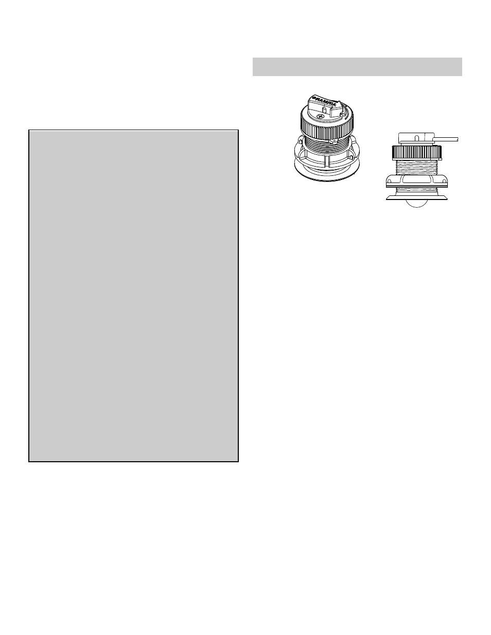
Low Profile P371
Flush P398
INSTALLATION INSTRUCTIONS
OWNER’S GUIDE &
Record the information found on the cable tag for future reference.
Part No.:___________________Date___________
Follow the precautions below for optimal product
performance and to reduce the risk of property
damage, personal injury, and/or death.
WARNING: Always wear safety goggles and a dust
mask when installing.
WARNING: The valve is not a watertight seal! Always
use the insert or the blanking plug secured with the
safety wire for a watertight seal.
WARNING: The O-rings must be intact and well
lubricated to make a watertight seal.
WARNING: Always attach the safety wire to prevent
the sensor insert or blanking plug from backing out in
the unlikely event that the cap nut fails or is screwed
on incorrectly.
WARNING: Immediately check for leaks when the boat
is placed in the water. Do not leave the boat unchecked
for more than three hours. Even a small leak may allow
considerable water to accumulate.
CAUTION: Never use a fairing with a plastic housing;
the protruding sensor would be vulnerable to damage
from impact.
CAUTION: Never pull, carry, or hold the sensor by its
cable; this may sever internal connections.
CAUTION: Never use solvents. Cleaners, fuel,
sealants, paint, and other products may contain strong
solvents, such as acetone, which attack many
plastics, greatly reducing their strength.
IMPORTANT: Please read the instructions completely
before proceeding with the installation. These
instructions supersede any other instructions in your
instrument manual if they differ.