Airmar P48W User Manual
Installation instructions owner’s guide, Tools & materials, Applications
Follow the precautions below for optimal
product performance and to reduce the risk of
property damage, personal injury, and/or death.
WARNING: Always wear safety goggles and a dust
mask when installing.
WARNING: When the boat is placed in the water,
immediately check for leaks around the screws and
any other holes drilled in the hull.
CAUTION: P48W—Operate at 200kHz only.
Operating at any other frequency will permanently
damage the transducer and/or the echosounder.
CAUTION: CHIRP transducer—Always operate the
transducer in water. Operating in air will allow the
transducer to overheat resulting in failure.
CAUTION: Never pull, carry, or hold the transducer by
its cable; this may sever internal connections.
CAUTION: Never strike the transducer with anything
except the palm of the hand to release it.
CAUTION: Never use solvents. Cleaner, fuel, sealant,
paint and other products may contain solvents that can
damage plastic parts, especially the transducer’s face.
IMPORTANT: Read the instructions completely
before proceeding with the installation. These
instructions supersede any other instructions in your
instrument manual if they differ.
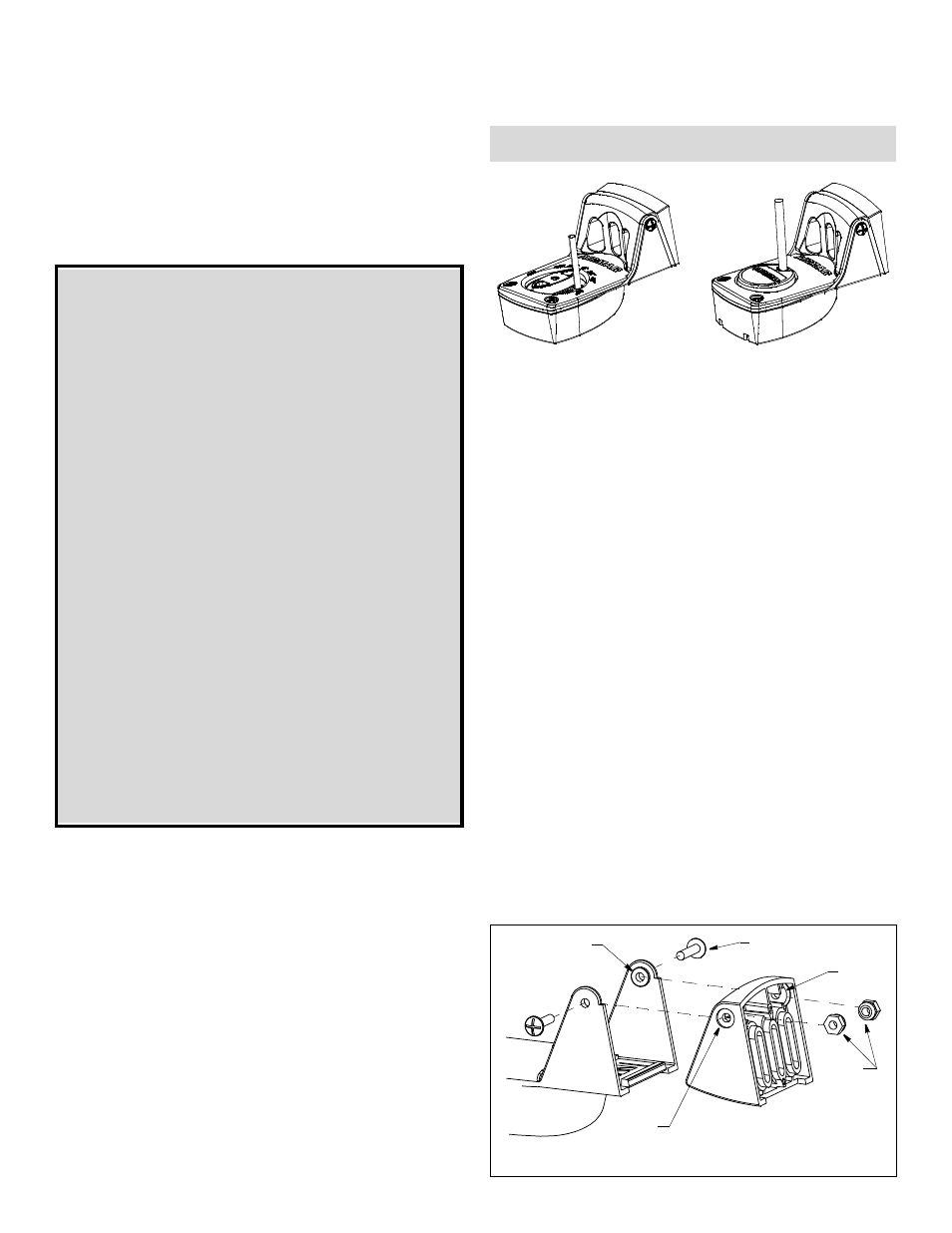
Figure 1. Attaching the bracket to the transducer
pivot post (2)
recess (2)
bracket
nuts
machine
screw (2)
slot (2)
Copyright © 2008 Airmar Technology Corp.
sensor
17
-4
99
-0
1 re
v.
0
6
01
/18
/13
Transom or Trolling Motor Mount
CHIRP or Adjustable Wide-beam Transducer
Models: P48W, TM130M, TM150M, TM210H
U.S. Patent 7,961,522. UK 2 414 077. U.S. Patents Pending
Tools & Materials
Safety goggles
Dust mask
Phillips screwdrivers
Pencil
Electric drill
Drill bits:
Bracket holes
4mm, #23, or 9/64"
Transom hole (optional)
18mm, 11/16", or 3/4"
24 mm or 15/16" or 1"
(Raymarine only)
Cable clamp holes
3mm or 1/8"
Masking tape
Angle finder (some installations)
Marine sealant (suitable for below waterline)
Straight edge
Grommet(s) (some installations)
Cable ties (some installations)
Band clamp
(trolling motor mount) Measure before purchasing ( Figure 9)
Water-based anti-fouling paint (mandatory in salt water)
Record the information found on the cable tag for future reference.
Part No._________________Date___________Frequency________kHz
INSTALLATION INSTRUCTIONS
OWNER’S GUIDE &
TM150M
P48W
Applications
• Recommended for boat up to 7m (22’) long
• Not recommended for boats with large inboard engine(s)
• P48W—Not recommended for stepped transoms because the
transducer will be difficult to adjust.
• Vertically orients sound beam on hull with deadrise angle up to 22°
• Adjusts to transom angles from 2
°
– 22
°
• Requires 89mm (3-1/2") of headroom to install
• Bracket protects sensor from frontal impact only
• P48W or TM150M—Trolling motor fitting adapts transducer for
use with a trolling motor or optional Portable Mount Kit
Transom Mount
Attaching the Bracket to the Transducer
1. Insert the sensor’s pivot posts into the recesses on the sides of
the bracket (see Figure 1).
2. Press the two nuts into the slots in the back of the bracket.
3. Align the holes in the sensor, bracket, and nuts. Insert the two
machine screws capturing the nuts. Tighten the machine screws
until the sensor will stay in the “up” (released) position unaided.
Mounting Location
CAUTION: Do not mount in line with or near water intake or
discharge openings or behind strakes, fittings, or hull irregularities
that will disturb the water flow.
CAUTION: Do not mount the sensor where the boat may be
supported during trailering, launching, hauling, or storage to avoid
damaging the transducer’s face.