Airmar S69—Transom Mount User Manual
Installation instructions owner’s guide, Models: s69, st69 applications, Tools & materials
17
-1
45
-0
1 re
v.
0
4
04
/12
/11
Transom Mount with Integral Bracket
Speed & Temperature Sensor
Models: S69, ST69
Applications
• Not recommended for boats with large inboard engine(s).
• Good operation from 4–50kn (5–58MPH)
• Adjusts to transom angles from 3
°
–16
°
Tools & Materials
Safety goggles
Dust mask
Digital level
Screwdrivers
Weak solvent (alcohol)
Straight edge
Electric drill
Drill bits:
Mounting holes
5.4mm, #3, or 13/64"
Transom hole (optional)
20mm or 13/16"
Cable clamp holes
3mm or 1/8"
Masking tape
Marine sealant (suitable for below waterline)
Putty knife
Pencil
Zip-ties
Water-based antifouling paint (mandatory in salt water)
Pretest
Connect the sensor to the instrument and spin the paddlewheel.
Check for a speed reading and the approximate air temperature. If
there is no reading(s) or it is inaccurate, check the connections
and repeat the test. If there is still no reading(s) or it is inaccurate,
return the product to your place of purchase.
Mounting Location
CAUTION: Do not mount in an area of turbulence or bubbles:
near water intake or discharge openings; behind strakes, struts,
fittings, or hull irregularities
CAUTION: Avoid mounting the sensor where the boat may be
supported during trailering, launching, hauling, or storage.
• For the best performance, the sensor must be in contact with
smooth water. To identify an area of clean water, observe the
water flow off the transom while the boat is underway.
• Mount the sensor as close to the centerline (keel) of the boat as
possible to ensure the sensor remains in the water when the
boat is turning.
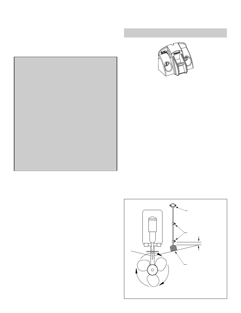
• Single drive boat—Mount at least 75mm (3") beyond the
swing radius of the propeller (see Figure 1). The starboard side
where the propeller blades are moving downward is preferred.
• Twin drive boat—Mount the sensor between the drives.
Figure 1. Mounting location on single drive boat
cable cover
cable clamps
50mm (2")
use double-sided tape
flush with the bottom
to hold the sensor
of the hull before installation
INSTALLATION INSTRUCTIONS
OWNER’S GUIDE &
Record the information found on the cable tag for future reference.
Part No._________________Date___________
Follow the precautions below for optimal product
performance and to reduce the risk of property
damage, personal injury, and/or death.
WARNING: Always wear safety goggles and a dust
mask when installing
WARNING: When the boat is placed in the water,
immediately check for leaks around the screws and
any other holes drilled in the hull.
CAUTION: Never pull, carry, or hold the sensor by the
cable as this may sever internal connections.
CAUTION: Never strike the sensor.
CAUTION: Never use solvents. Cleaners, fuel, paint,
sealants, and other products may contain strong
solvents, such as acetone, which attack many plastics
greatly reducing their strength.
IMPORTANT: Please read the instructions completely
before proceeding with the installation. These
instructions supersede any other instructions in your
instrument manual if they differ.