Airmar Splash-proof Junction Box User Manual
Installation instructions, Junction box, Terminal style applications
17
-0
37
-0
1 re
v.
04
12
/14
/10
WARNING: Always wear safety goggles and a dust
mask to avoid personal injury.
CAUTION: High Voltage Charge
The depth transducer may be storing a high voltage
charge. Accidental discharge could destroy the speed
sensor.
IMPORTANT: Please read these instructions
completely before proceeding with the installation.
These instructions are to be used in conjunction with
your instrument manual and the instructions provided
with your transducer(s), sensor, or other components.
Junction Box
Terminal Style
Applications
•
To provide a water, fog, and salt-resistant splice.
•
To splice marine cables up to 7.5mm (5/16") in diameter.
•
To splice marine cables with up to eight wires.
(Two crimp connectors are included for additional wires.)
•
To splice Airmar TRIDUCER
®
multisensor and other Airmar
cables.
Pre-Installation Test
NOTE: For Airmar Products Only
1. Connect the transducer or multisensor to the echosounder with
the transducer in the water and aimed at the bottom. Check for
a depth reading on the instrument (and temperature reading if
applicable).
2. To check the speed and temperature functions, connect the
sensor to the instrument. Spin the paddlewheel and check for a
reading of several knots. Check for the approximate air temp.
3. If a test produces no reading, check all the connections and
repeat the test. If a function (depth, speed, or temperature) is
inoperative, do not install the unit; return it to the dealer.
Tools & Materials
Safety goggles
Dust mask
Screwdrivers: Phillips and blade
Pencil
Drill
Drill bit: 3mm or 1/8"
Box-cutter knife (some installations)
Cutting pliers
Alcohol
Wire strippers
Crimping pliers (nine or ten-wire cables)
Petroleum jelly (nine or ten-wire cables)
Cable ties
Parts Needed
CAUTION: Do not puncture unused grommets.
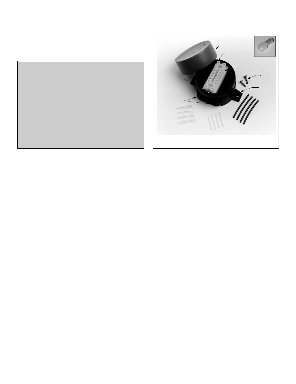
1. Remove the red cap and the contents of the junction box
including the terminal block (see Figure 1).
2. The type of sensor and the size of the cable determine which
instructions to follow (see Table 1 on page 4). Determine the
grommets that will be needed. Using a small Phillips
screwdriver, puncture the center of the appropriate grommets.
NOTE: The small grommets (marked 3-5) provide moisture
sealing for cables from 3.5–5mm (1/8–3/16"). The large
grommets (marked 5-7) provide moisture sealing for cables
from 5–7.5mm (3/16–5/16"). Both set of grommets can
accommodate smaller cables than suggested, but the sealing
will be less effective. Larger cables can be used, but insertion
will be difficult.
3. Set aside the sleeving that will be needed.
Mounting Location
1. Select a convenient dry mounting location along the cable route,
preferably 1–1.5 m (3–5') from the transducer/sensor to
facilitate future replacement.
2. Position the junction box so the grommets are easily accessible
to the cable. Mark the location of the mounting holes.
3. At the marked location, drill two 3mm or 1/8" holes
approximately 10mm (3/8") deep. Do not fasten the junction
box in place at this time.
connector
black sleeving
large diameter
sleeving
small diameter
sleeving
terminal block
tab (2)
grommet (4)
Figure 1. Junction box and contents
terminal
terminal screw
mounting screws
mounting
block
screws
(16)
screw (2)
cap
INSTALLATION INSTRUCTIONS
Copyright © 2009 Airmar Technology Corp.