Airmar Switchboxes—SB264, SB260 User Manual
Installation instructions owner’s guide, Switchbox with remote switch
WARNING: Always wear safety goggles and a dust
mask when installing to prevent personal injury.
WARNING: The power must be “OFF” before
proceeding with the installation.
WARNING: A safe installation requires a 0.5 amp fast-
blow fuse or circuit breaker. Failure to do so may
damage the product and/or result in fire, damage to
the boat, and/or personal injury.
CAUTION: To reduce electrical interference from
other electrical wiring and any on-board equipment with
strong magnetic fields such as radar equipment, radio
transmitters, boat engines, generators, etc., separate
the cables by at least 1m (3').
CAUTION: Be careful not to tear the cable jackets
when passing them through bulkheads and other
parts of the boat. Use grommets to prevent chaffing.
Use deck glands to prevent water seepage into the
boat.
CAUTION: Use a multimeter to check the polarity and
the connections to the 10 - 32 VDC power supply
before applying power to the transducer(s).
IMPORTANT: Please read the instructions completely
before proceeding with the installation. These
instructions supersede any other instructions in your
instrument manual if they differ.
17
-49
8-0
1 r
ev.02
12
/1
4/1
0
Switchbox with Remote Switch
Models: SB260, SB264
Applications
• Single transmission line transducers and echosounders only
• 1kW echosounders only. Do not use with 2 kW echosounders.
• SB260 switches between:
- Two depth transducers connected to one echosounder. The
transducers must use C32 or C332 cable.
- Two echosounders connected to one depth transducer. The
echosounder must be dual-frequency with a single
transmission-line. The transducer must use C32 or C332
cable.
• SB264
Switches between a wide-beam and a narrow-beam depth
transducer connected to one echosounder. Pair a wide-beam
SS264W with one of the narrow-beam models such as: B258,
B260, or M260. Both transducers must have C32 or C332
cable.
Tools & Materials
Safety glasses
Dust mask
Grommets (some installations)
Deck glands (some installations)
Cutting pliers
Phillips screwdrivers
Pencil
Electric drill
Drill bits:
Switchbox
3mm or 1/8"
Remote switch
11mm or 1/2" spade bit
Sandpaper
Weak solvent (such as alcohol)
Wire strippers
Heat shrink tubing
Blade screwdriver
Pliers
Adjustable wrench
Cable ties (some installations)
Locating Switchbox, Remote Switch & Cables
IMPORTANT: Be sure to allow an extra 25 cm (10") of cable to
make the connections within the switchbox.
Switchbox—Select a convenient dry mounting location for the
water-resistant switchbox about 1–2m (3' – 5') from the echo-
sounder(s).
• Retrofit—If the transducer(s) and echosounder(s) are already
installed, select a location with easy access to the cable(s). Be
sure the cable(s) will be long enough to make the necessary
connections. Allow an extra 25 cm (10") for wiring ease.
• New installation—Install the transducer(s) and echosounder(s)
before connecting the switchbox. Plan the cable runs.
Remote Switch—Locate the remote switch on the dash panel or
other convenient location near the echosounder. Check the back-
side for any obstructions such as cables and wires.
• Minimum clearance on backside 36mm (1-1/2")
• Maximum panel thickness6mm (1/4”)
INSTALLATION INSTRUCTIONS
OWNER’S GUIDE &
Copyright © 2008 Airmar Technology Corp.
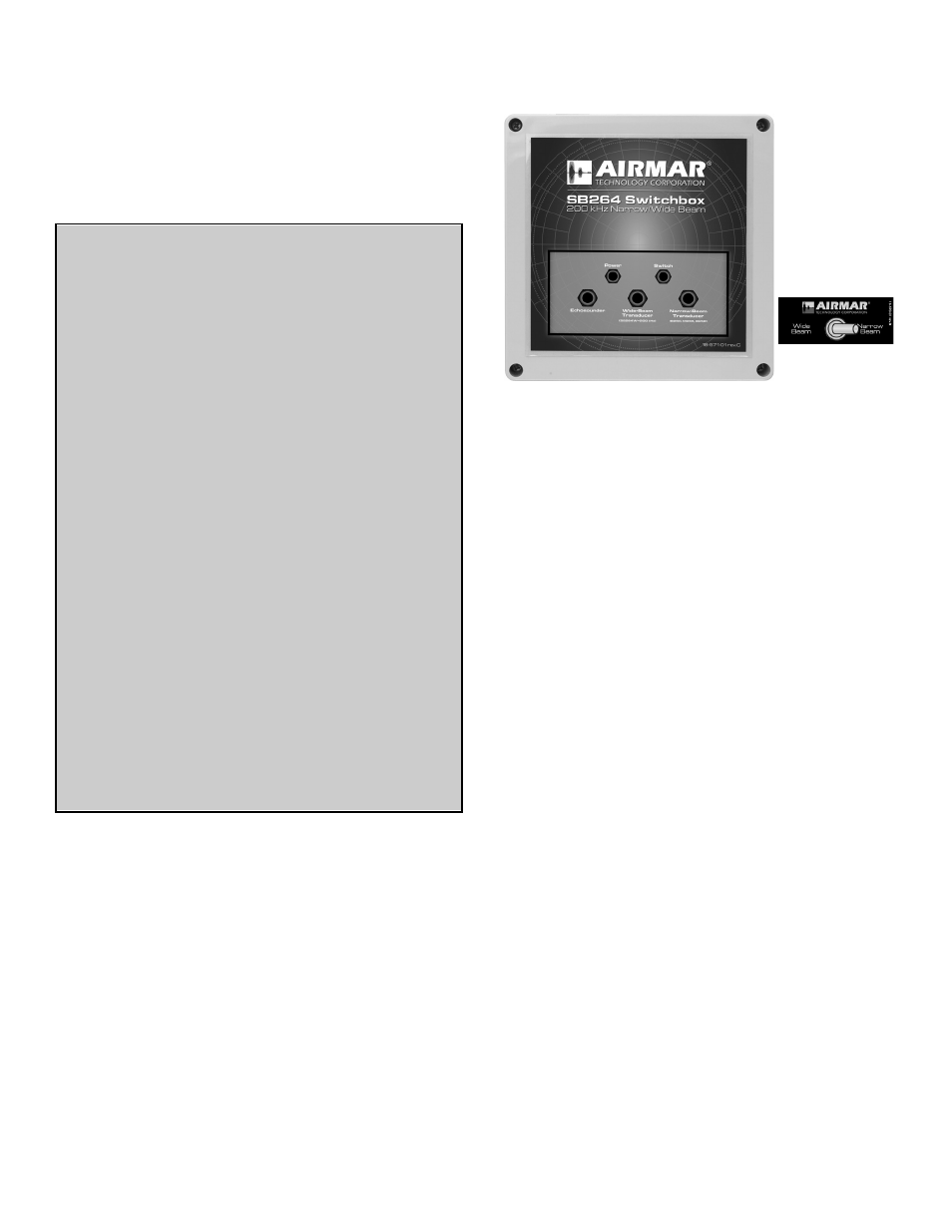
Figure 1. SB264 Switchbox and remote switch