Bestobell Steam Universal Trap User Manual
Pre-installation, Installation, Universal traps
3170 Wasson Road • Cincinnati, OH 45209 USA
Phone 513-533-5600 • Fax 513-871-0105
[email protected] • www.bestobellsteamtraps.com
Universal Traps
Installation & Maintenance Instructions for
Bestobell Steam Universal Traps
Warning: Bestobell Steam products must only be used, installed and repaired in accordance with these Installation
& Maintenance Instructions. Observe all applicable public and company codes and regulations. In the event of leak-
age or other malfunction, call a qualified service person; continued operation may cause system failure or a general
hazard. Prior to servicing equipment, disconnect, shut off, drain and/or bypass all pressurized fluids.
Pre-Installation
1. Blow out piping to remove any scale or dirt.
2. Verify that your Bestobell steam trap will meet system
conditions by checking the nameplate for operating
differential pressure and maximum pressure and tem-
perature limits of the trap body.
3. The pipe connector (25) can be oriented in many
positions as long as the trap mounting surface is either
horizontal or vertical when the trap body is mounted.
See orientation as shown below.
4. The flow arrow in the pipe connector must be in the
direction of the flow, otherwise the trap will not operate
because the integral check valve will not allow flow in
reverse direction.
Installation
1. Once the pipe connector has been installed, the
steam trap can be mounted to it using the two bolts
(17) with a suitable anti-seize compound applied to
them.
2. The trap should be oriented as shown in Figure 1 by
rotating the swivel flange (11) to align with the bolts
in the connector. For horizontal trap mounting, the
word “TOP” on the body casting (1) should be facing
up.
3. Secure the two bolts initially by hand and then tight-
ening to 35 ft-lbs using a 9/16” wrench.
4. Be sure to check that both inner and outer gaskets
are in position before making connection.
5. Pipe connections can be purchased with strainer and
an optional integral blowdown valve.
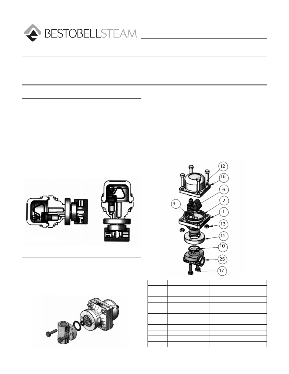
Figure 1
Item
Part Name
Material
Qty
1
Body
CF8 SST
1
2
Body Gasket
Grafoil
1
6
Control Element
SST
1
9
C/E Gasket
Grafoil
1
10
Snap Ring
303 SST
1
11
Swivel Flange
304 SST
1
12
Cover Bolts
GR8
4
13
Cover Nuts
GR8
4
16
Cover
CF8 SST
1
17
Connector Bolts
GR8
2
25
Connector
CF8 SST
1