H3C Technologies H3C S10500 Series Switches User Manual
Chassis views and technical specifications, Installing the switch, Installing frus
Item
LSUM1AC2500
LSUM1DC2400
Rated input
voltage range
100 VAC to 240 VAC
@ 50/60 Hz
–48 VDC to –60 VDC
Maximum
input current
16 A
60 A
1200 W (110 VAC)
2500 W (220 VAC)
2400 W
LSUM1AC1200
100 VAC to 240 VAC
@ 50/60 Hz
16 A
1200 W
This installation quick start provides basic instructions for installing the
S10506 and S10510 switches. For detailed installation procedures, see
H3C S10500 Switch Series Installation Guide.
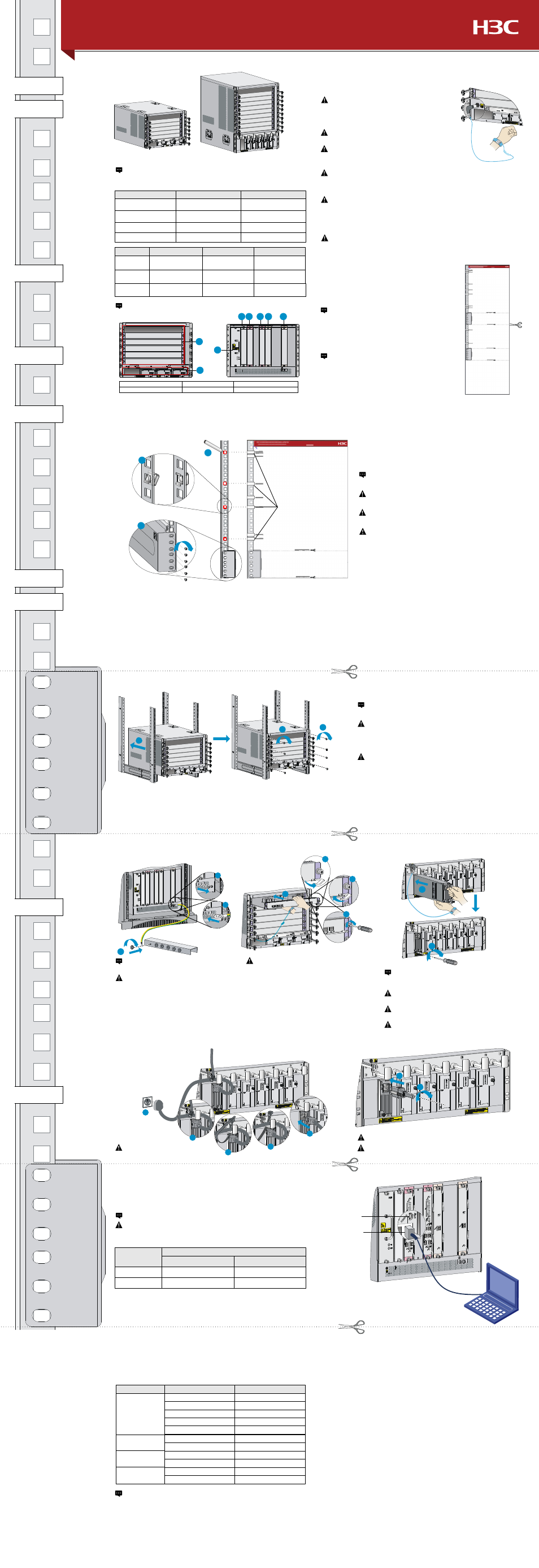
Chassis views and technical specifications
The S10500 switches can only be used indoors. To make sure the switch
operates correctly and to prolong its service lifetime, the installation site must
meet the requirements of load-bearing, temperature, humidity, cleanness, EMI,
grounding, power module, and space. For more information, see H3C S10500
Switch Series Installation Guide.
Cutting the cage nut installation template
Safety Recommendations
Examining the installation site
When the S10500 switches are installed in an enclosed cabinet, the distance
between the front rack posts and the front door must be greater than 100 mm
(3.94 in) for installing cable management brackets. The distance between the
front rack posts and the rear door must be greater than 710 mm (27.95 in) for
the chassis with cards installed.
Installing the switch
If you use the H3C slide rails for installation of the
S10506 switch, please cut this guide along the dotted
line marked as “For S10506 that uses H3C slide rails”.
If you use other slide rails, please cut this guide along
the dotted line marked as “For S10506 that uses non-
H3C slide rails”.
Installing cage nuts and slide rails to the rack
Align the cage nut installation template with the rack posts to
identify the installation holes on the rack posts.
Installing the switch in the rack
Installing FRUs
Installing a power module
Connecting power cords
Log in to the switch
Connecting the console cable
Powering on the switch
Item
S10506
S10510
Weight
(full configuration)
< 90 kg (198.41 lb)
< 130 kg (286.60 lb)
Height (H)
353 mm (13.90 in)
(8 RU)
620 mm (24.41 in)
(14 RU)
Width (W)
440 mm (17.32 in)
440 mm (17.32 in)
Depth (D)
660 mm (25.98 in)
660 mm (25.98 in)
S10506
S10510
To avoid any equipment damage or bodily injury caused by improper use, read the
following safety recommendations before installation. Note that the recommendations
do not cover every possible hazardous condition.
To avoid power module damage, support the bottom
of a power module instead of holding its handle for
moving the power module.
Do not install power modules of different models on
the same switch.
Connecting a DC power cord
Before you connect the power cord,
make sure the circuit breaker for the
power cord is switched off.
When connecting the DC power cords to the DC wiring terminals,
make sure both + end and – end of the circuit breaker at the power
input end are off.
Make sure each power cord has a separate circuit breaker.
You can only log in through the console port for your first login to the switch.
1.
Make sure the power cord is connected to the power source.
2.
Turn on the circuit breaker.
3.
Power on the switch.
4.
To make sure the switch is operating correctly, verify the LED status on the
switch according to the descriptions in the following table.
Obtaining documentation
To avoid equipment damage or even bodily injury, use at least
two people to lift a switch. If necessary, use a mechanical lift.
Do not hold the fan tray handle, the power module handle, the
back cover of the chassis, or the air vents of chassis. Any attempt
to carry the switch with these parts might cause equipment
damage or even bodily injury.
After placing the switch on the slide rails, do not immediately
loosen your hands because a fall might occur and damage the
switch, and even cause bodily injury.
Use the provided grounding cable (yellow-
green grounding cable).
Connect the grounding cable to the grounding
system in the equipment room. Do not connect
it to a fire main or lightning rod.
To prevent the electronic components from being
damaged by the electrostatic discharge (ESD), always
wear an ESD wrist strap and make sure it is correctly
grounded before you touch the switch, cards, or PCB.
Do not install the switch, FRUs, or power cords when the
switch is powered on.
Before powering on the switch, verify that the switch is
correctly grounded. Otherwise, equipment damage or bodily
injury might occur.
Provide a circuit breaker for each power module and
verify that the circuit breaker is off before installation.
Take the following steps to get related documents from the H3C website at
www.h3c.com.
1.
Go to http://www.h3c.com/portal/Technical_Documents.
2.
Choose the desired product category and model.
Before installing a card to the chassis, make sure
the connectors on the card are not broken or
blocked to avoid damaging the backplane.
MPU
Switching fabric
module
Power module
Fan tray
Module
LED
Status
LINK/ACT
Flashing or steady on
OK
Steady on
FAIL
Off
RUN
Flashing
ALM
Off
RUN
Flashing or steady on
ALM
Off
Power input
Steady green
Power output
Steady green
OK
Steady on
FAIL
Off
You can verify only the link state and data transmitting and receiving state
according to the LPU LED status.
For more information about LED status of all cards, see H3C S10500 Switch
Series Installation Guide.
Make sure the bottom edge of the slide rail aligns with the middle
of the narrower metal area between the installation holes.
You can identify the front ends of the left and right H3C slide
rails by the F/L and F/R marks on the slide rails, respectively.
Before you fasten the captive screws to secure the
power module, press the handle inwards until the
handle seats into the slot.
If you use non-H3C slide rails, make sure the associated dotted
line aligns with the top edge of your slide rails.
If you connect your console terminal to both the console port and the
USB console port, only the USB console port can be used for
communication.
Copyright © 2014, Hangzhou H3C Technologies Co., Ltd
USB console port
Console port
(1) LPU slots
(2) Power module slots
(3) Fan tray slot
(4) PoE power entry module slot
(5) MPU slots
(6) Switching fabric module slots
The slot allocations for all FRUs on the S10510 and S10506 are the same.
This guide uses the S10506 as an example.
Port type
Switch end
PC or terminal end
Console port
RJ-45 connector
DB-9 female connector
USB Console port
Mini-USB A/B type connector
USB A type connector
Connector type
Grounding the switch
Installing cards
Connecting an AC power cord
To ensure good ventilation, install a blank filler panel over an unused slot.
Maximum
output power
If you use the H3C slide rails for installation of the
S10510 switch, please cut this guide along the dotted
line marked as “For S10510 that uses H3C slide rails”.
If you use other slide rails, please cut this guide along
the dotted line marked as “For S10510 that uses non-
H3C slide rails”.
1
2
3
4 5
6
5
6
1
2
3
S10506 cage nut
installation holes
S10510
installation hole 6
S10510
installation hole 3
S10510
installation hole 4
S10506
installation hole 1
S10506
installation hole 2
S10506
installation hole 3
S10506
installation hole 4
S10510
installation hole 1
S10510
installation hole 2
S10510
installation hole 5
H3C S10506&S10510 Switches Installation Quick Start -5PW102
(This guide also can be used as a cage nut installation template)
Installing the switch
BOM:3104A0F0
For S10506 that uses non-H3C slide rails
For S10506 that uses H3C slide rails
For S10510 that uses non-H3C slide rails
For S10510 that uses H3C slide rails
2
2
1
1
2
3
4
1
2
1
2
16A
1
2
4
5
3
Installing the switch
Installing the switch
3
2
1