H3C Technologies H3C S10500 Series Switches User Manual
Page 13
Advertising
5
•
The installation site has a good cooling system.
•
Verify that the airflow design of the chassis meets the airflow design of the installation site.
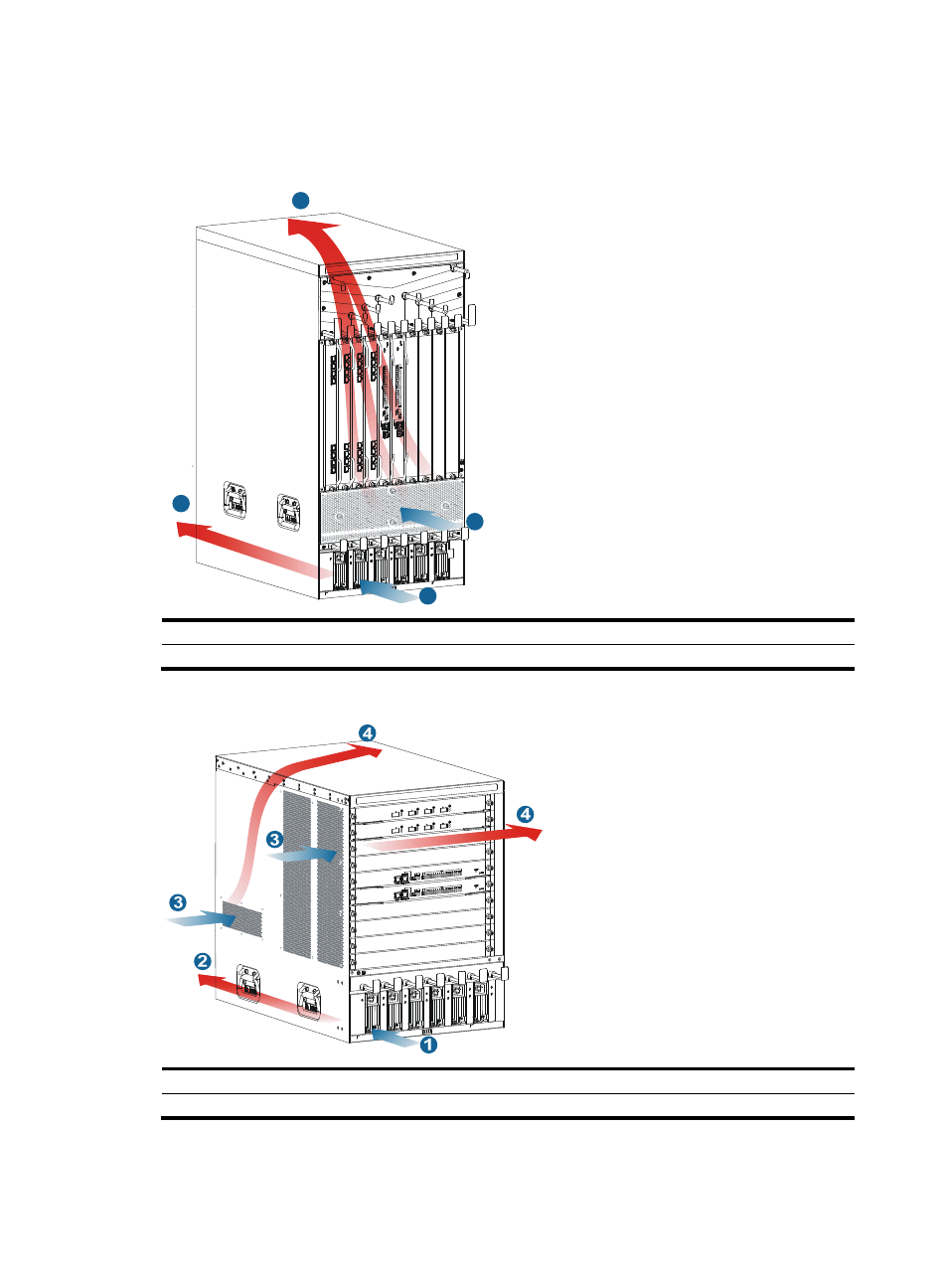
Figure 1 Airflow through the S10508-V chassis
(1) Power supply air intake vents
(2) Power supply air exhaust vents
(3) Chassis air intake vents
(4) Chassis air exhaust vents
Figure 2 Airflow through other S10500 switch chassis
(1) Power supply air intake vents
(2) Power supply air exhaust vents
(3) Chassis air intake vents
(4) Chassis air exhaust vents
2
4
1
3
Advertising
This manual is related to the following products: