H3C Technologies H3C S9800 Series Switches User Manual
1 introduction, 2 installation procedures
Manual version: 6PW101-20150202 BOM:
3105A02Y
i
H3C LSVM1BSR10 adjustable slide rails installation guide
1 Introduction
The H3C LSVM1BSR10 adjustable slide rails have a load-bearing capacity of 200 kg (440.92 lb).
When the load is less than 100 kg (220.46 lb), you can adjust the slide rails in the range of 630 mm
(24.80 in) to 900 mm (35.43 in). When the load is greater than or equal to 100 kg (220.46 lb), you can
adjust the slide rails in the range of 630 mm (24.80 in) to 850 mm (33.46 in).
The H3C LSVM1BSR10 adjustable slide rails are applicable only to four-post racks. To attach the slide
rails to a rack, make sure the rack depth is in the length range of the slide rails.
2 Installation procedures
The installation of slide rails might vary by rack type. The following installation procedure is for your
reference only.
To install a slide rail:
1.
Read the signs on the slide rail to avoid making a mistake.
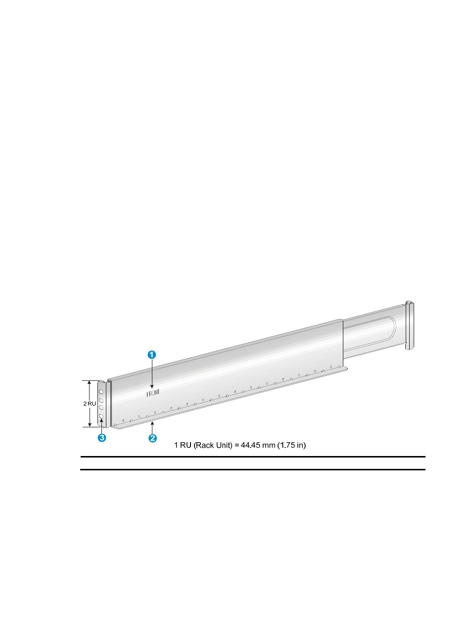
Figure 1 Left slide rail
(1) Sign
(2) Guide rail
(3) Installation hole
2.
Mark the position on the rack for installing the slide rail, as shown in
a.
Insert the positioning tab at the bottom of the slide rail into the lowest square hole within the 2U
space on the rack post.
Ensure that the installation holes on the slide rail are aligned with the square holes on the rack
post.
b.
Each rack post requires four screws to fix the slide rail. You only need to mark the uppermost
square hole and lowermost square hole for installation.
c.
Mark the square holes at the same height on the other three rack posts.